
The third-generation Mercedes-Benz C-Class made its world premiere in Stuttgart in January 2007. The W204 sedan features a highly refined aesthetic and improved aerodynamics. A large radiator grille, redesigned lighting assemblies, and a front bumper with enlarged air intakes give it a more aggressive stance. This article provides a comprehensive overview of the fuse box diagrams for the Mercedes-Benz C-Class W204 (3rd Gen; C180, C230, C280, C350, C63 AMG) covering the 2007, 2008, 2009, 2010, 2011, 2012, 2013, and 2014 model years.

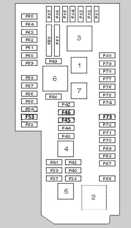
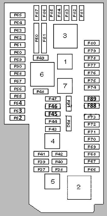
Below you will find the locations and photographs of the power distribution boxes. The fuses protecting the “Cigarette Lighter” and “Fuel Pump” circuits are highlighted in bold.
Luggage Compartment
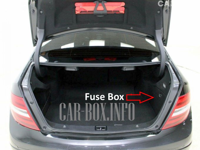
Location of the fuse box (sedan).
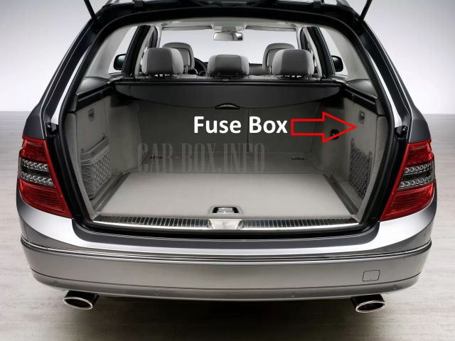
Location of the fuse box (estate/wagon).
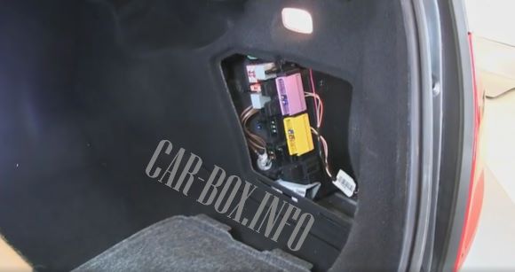
Example of access.
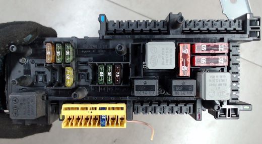
General view.
| Diagram | ||
|---|---|---|
| Models before June 2009 | ||
|
||
| No. | Circuit / Component | A |
| F37 | Supplemental Restraint System (SRS) | 7.5 |
| F38 | 15 | |
| F39 | Left rear door control module | 30 |
| F41 | Right rear door control module | 30 |
| F42 | 20 | |
| F44 | Multifunction seat switch (front right) | 30 |
| F45 | Multifunction seat switch (front left) | 30 |
| F46 | 7.5 | |
| F49 | Rear window defroster | 40 |
| F50 | 50 | |
| F51 | 50 | |
| F53 | Trailer control module | 30 |
| F54 | Trailer control module | |
| F56 | Trailer control module | 15 |
| F57 | 20 | |
| F58 | 30 | |
| F59 | Parking assist control module | 7.5 |
| F61 | Tailgate/trunk lid power closing module | 40 |
| F67 | Audio amplifier | 40 |
| F70 | Tire Pressure Monitoring System (TPMS) control module | 5 |
| F71 | Cigarette lighter fuse (Mercedes-Benz W204: C180, C230, C280, C350, C63 AMG) | 15 |
| F72 | 15 | |
| F74 | Keyless entry and engine start control module | 15 |
| F76 | Auxiliary power outlet | 15 |
| F79 | Parking assist control module | 7.5 |
| F81 | Audio interface control module | 7.5 |
| F83 | Tele Aid / Emergency call system | 7.5 |
| F84 | Audio system | |
| F87 | Tele Aid / Emergency call system | 7.5 |
| 3 | Rear window defroster relay | |
| 6 | Power seat relay | |
| Models after June 2009 | ||
|
||
| No. | Circuit / Component | A |
| F37 | Supplemental Restraint System (SRS) | 5 |
| F38 | 15 | |
| F39 | Left rear door control module | 30 |
| F41 | Right rear door control module | 30 |
| F42 | Fuel pump control module (fuel pump fuse) | 20 |
| F43 | 7.5 | |
| F44 | Multifunction seat switch (front right) | 30 |
| F45 | Multifunction seat switch (front left) | 30 |
| F46 | 7.5 | |
| F49 | Rear window defroster | 40 |
| F50 | Supplemental Restraint System (SRS) | 50 |
| F51 | 50 | |
| F53 | Trailer control module | 30 |
| F54 | Trailer control module | |
| F56 | Trailer control module | 15 |
| F57 | 20 | |
| F58 | 20 | |
| F59 | PARKTRONIC | 5 |
| F60 | Multicontour seat pneumatic pump | 7.5 |
| F61 | Tailgate/trunk lid power closing module | 40 |
| F62 | 30 | |
| F63 | 30 | |
| F65 | Suspension control module | 15 |
| F67 | Audio amplifier | 30 |
| F70 | Tire Pressure Monitoring System (TPMS) control module | 5 |
| F71 | Cigarette lighter fuse (Mercedes-Benz W204: C180, C230, C280, C350, C63 AMG) | 15 |
| F72 | 15 | |
| F73 | 7.5 | |
| F74 | Keyless entry and engine start control module | 15 |
| F75 | Auxiliary heater control module | 20 |
| F76 | Auxiliary power outlet | 15 |
| F81 | Audio interface control module | 7.5 |
| F82 | Telephone | 5 |
| F83 | Tele Aid / Emergency call system | 7.5 |
| F84 | 7.5 | |
| F87 | Tele Aid / Emergency call system | 7.5 |
| F89 | 20 | |
| F91 | Up to 06/2010: Not used | |
| 3 | Rear window defroster relay | |
| 6 | Power seat relay | |
Passenger Compartment
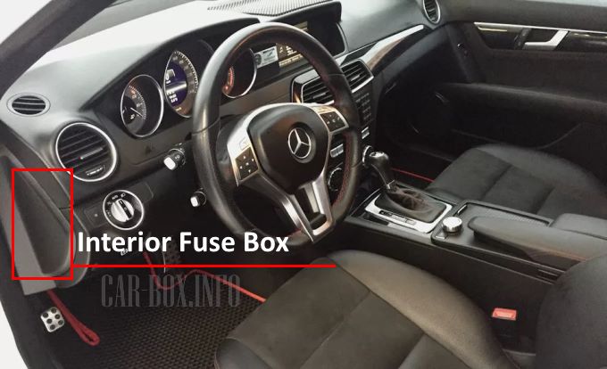
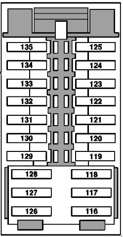
The power distribution box is located on the driver's side at the outer edge of the instrument panel, behind a protective cover.
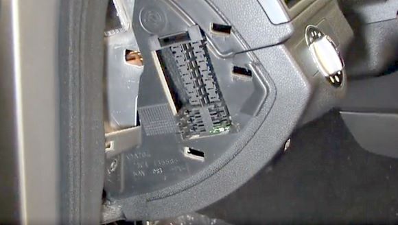
Example of access.
| Mercedes-Benz W204 Interior Fuse Box Diagram | ||
|---|---|---|
|
||
| No. | A | Description |
| 116 | 30 | Driver's seat control module (up to 05/31/2009) |
| 117 | 15 | Adaptive Damping System (ADS) control module (up to 05/31/2009) |
| 118 | - | Spare |
| 119 | 7.5 | Rear climate control blower motor (up to 05/31/2009) |
| AMG Performance Media control module (up to 06/01/2012) | ||
| 120 | - | Spare |
| 121 | - | |
| 122 | - | |
| 123 | 10 | Steering column module |
| 124 | - | Spare |
| 125 | - | |
| 126 | 30 | Front passenger seat control module (up to 05/31/2009) |
| 127 | - | Spare |
| 128 | - | |
| 129 | 20 | Oil cooler fan motor relay (M156 engine; up to 05/31/2009) |
| 130 | - | Spare |
| 131 | - | |
| 132 | - | |
| 133 | - | |
| 134 | - | |
| 135 | - | |
Engine Compartment
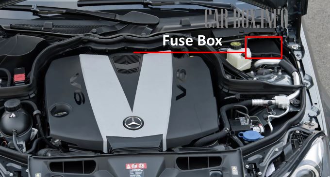
The power distribution box is located on the upper right side of the engine compartment.
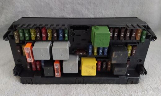
General view of the Mercedes-Benz C-Class W204 underhood fuse box.
| Diagram | ||
|---|---|---|
|
||
| No. | Relay Description | |
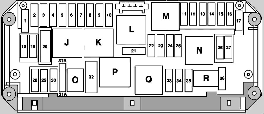
| J | Circuit 15 relay (ignition) | |
| K | Circuit 15R relay (accessory) | |
| L | Spare | |
| M | Starter relay (Circuit 50) | |
| N | Engine control relay (Circuit 87) | |
| O | Horn relay | |
| P | Secondary air injection pump relay | |
| Q | Oil cooler fan relay | |
| R | Chassis control relay (Circuit 87) | |
| No. | A | Description |
| 1 | 25 | Electronic Stability Program (ESP) control module |
| 2 | 30 | Left front door control module |
| 3 | 30 | Right front door control module (up to 03/31/2010) |
| 4 | 7.5 | Fuel pump module (gasoline engines) |
| Left fuel pump module (M156 engine) | ||
| Right fuel pump module (M156 engine) | ||
| Fuel filter water-in-fuel sensor and heater (OM642, OM651 engines) | ||
| Fuel filter water-in-fuel sensor and heater control module (OM651 engine up to 05/31/2010, OM646 engine) | ||
| 20 | Headlamp control module (from 03/01/2011) | |
| 5 | 7.5 | Rear Signal Acquisition and Actuation Module (SAM) |
| Rear differential cooling pump relay (M156 engine from 07/01/2011) | ||
| Exterior lamp switch (from 12/01/2009) | ||
| 6 | 10 | CDI control module (diesel engines) |
| ME-SFI control module (gasoline engines) | ||
| 7 | 20 | Starter |
| 8 | 7.5 | Supplemental Restraint System (SRS) control module |
| 9 | 15 | 12V socket in the glove compartment |
| 10 | 30 | Windshield wiper motor |
| 11 | 7.5 | Audio display / COMAND |
| Audio control panel / COMAND | ||
| Navigation module cradle | ||
| 12 | 7.5 | Climate control module |
| Upper control panel | ||
| 13 | 7.5 | Steering column module |
| Multifunction camera (from 03/01/2011) | ||
| 14 | 7.5 | Electronic Stability Program (ESP) control module |
| 15 | 7.5 | Supplemental Restraint System (SRS) |
| Passive safety systems | ||
| 16 | 5 | Data Link Connector (DLC) / OBD-II port (up to 05/31/2009) |
| Cellular telephone pre-installation (up to 2008) | ||
| Electronic Selector Lever Module (ESM) (722 transmission) | ||
| 17 | 30 | Panoramic roof control module |
| Overhead control panel | ||
| 18 | 7.5 | Exterior lamp switch (up to 2008) |
| Upper control panel (from 03/01/2011) | ||
| LIN bus power distribution for climate control (up to 02/28/2011) | ||
| Interior wiring harness connector for rear lighting | ||
| 19 | 20 | Electronic Steering Lock (ESL) |
| Electronic Ignition Switch (EIS) | ||
| 20 | 40 | Electronic Stability Program (ESP) control module |
| 21 | 7.5 | Brake light switch |
| Glove compartment illumination switch | ||
| Front passenger seat occupancy sensor (AKSE / WSS) | ||
| Electronic Toll Collection (ETC) system pre-installation (Japan) | ||
| 22 | 15 | Engine cooling fan module |
| Engine and interior wiring harness connector | ||
| Circuit 87 M2e terminal (M271 engine, South Korea; M272 engine, USA) | ||
| ME-SFI control module (M271 engine; South Korea) | ||
| Purge control valve (M271 engine, South Korea; M272 engine, USA) | ||
| CDI control module (OM642, OM646 engines) | ||
| Crankcase ventilation heater (OM642 engine) | ||
| Circuit 87 terminal (OM646 engine) | ||
| 23 | 20 | Engine and interior wiring harness connector |
| Rear SAM control module (diesel engines) | ||
| CDI control module (diesel engines up to 2008) | ||
| Circuit 87 terminal (diesel engines up to 2008) | ||
| Circuit 87 M1e terminal (M271 engine up to 2008) | ||
| Circuit 87 M1i terminal (M272 engine up to 2008) | ||
| 24 | 15 | Engine and interior wiring harness connector |
| Radiator shutter actuator (OM642 engine) | ||
| CDI control module (OM646 engine) | ||
| Circuit 87 M1i terminal (M272 engine up to 2008) | ||
| Circuit 87 terminal (diesel engines up to 2008) | ||
| 25 | 15 | ME-SFI control module (M156, M271, M272, M274, M276 engines) |
| Upstream oxygen sensor (OM651 engine) | ||
| Exhaust gas treatment control module (OM651 engine) | ||
| 26 | 20 | Audio module |
| Audio module with Auto-Pilot system | ||
| COMAND module | ||
| 27 | 7.5 | Electronic Ignition Switch (EIS) |
| Electronic Steering Lock (ESL) (up to 2008) | ||
| CDI control module (diesel engines) | ||
| ME-SFI control module (gasoline engines) | ||
| 28 | 7.5 | Instrument cluster |
| 29 | 10 | Right front headlamp |
| 30 | 10 | Left front headlamp |
| Engine and interior wiring harness connector (OM642 engine) | ||
| 31A | 15 | Left horn |
| Right horn | ||
| 31B | 15 | Left horn |
| Right horn | ||
| 32 | 40 | Secondary air injection pump (M156, M271, M272 engines) |
| 33 | 10 | Transmission Control Module (TCM) (722.6 transmission) |
| Fully Integrated Transmission Control (VGS) (722.9 transmission) | ||
| 34 | 7.5 | Fuel pump control module (M274, M276 engines), (M271, M272, OM651 from 06/01/2009), (OM642 from 12/01/2009) |
| 35 | 5 | Electronic Stability Program (ESP) (from 2009) |
| 36 | 7.5 | DISTRONIC control module |
| Electrohydraulic power steering pump (from 2009) | ||

Splendid diagram, saved an awful lot of time digging out wiring circuit data. Thanks for posting this vital must have info.