The Audi A3 (8P) was introduced in 2003 at the Geneva Motor Show. Initially, the model was available only as a 3-door hatchback, in July 2004 a 5-door version (Sportback) appeared, and in 2008 - a convertible. Restyling took place in 2005, 2008 and 2010. In this article, we will take a detailed look at the fuse diagrams for the the Audi A3 2nd generation (8P): 2002, 2003, 2004, 2005, 2006, 2007, 2008, 2009, 2010, 2011, 2012 with engines 1.2 TSI, 1.4 TFSI, 1.6 8V, 1.6 FSI 16V, 1.6 8V E-Power, 1.6 TDI, 1.8 TFSI, 1.9 TDI 8V, 1.9 TDI 8V DPF, 2.0 FSI 16V, 2.0 TDI, 2.0 TDI 16V, 2.0 TFSI, 3.2 VR6, RS3(2.5 TFSI).

Here you will find the locations and photos of distribution boxes. The fuses responsible for the “Cigarette lighter” and “Fuel Pump” are highlighted in bold.
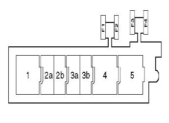
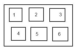
In the passenger compartment
Fuse box
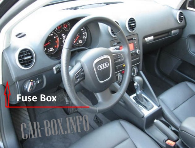
Located on the driver's side at the end of the dashboard behind a plastic cover.

Access example.

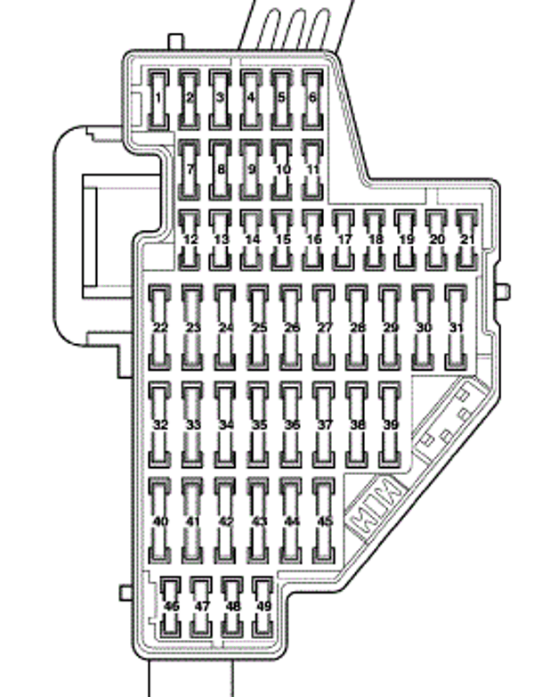
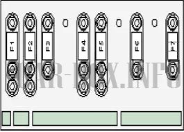
General view of the distribution box.
| Diagram | ||
|---|---|---|
|
||
| No. | Description | A |
| F1 | Diagnostic connector, engine management system, headlight range control, light switch, trailer electrical control unit | 10 |
| F2 | Automatic transmission control system, manual transmission (DSG), ABS system, brake light switch (brake pedal position sensor), diagnostic unit, engine management system, 4WD electronic control unit, power steering | 10 |
| F3 | Safety bag | 5 |
| F4 | Engine Oil Condition Sensor, Garage Door Remote Control System, Interior Rearview Mirror, Navigation System, Seat Heaters, Heating/Air Conditioning System, Parking Control Unit/Control, Reversing Lights (with Manual Transmission), TCS/ESP Master Switch, Control Unit seat occupant detection systems, tire pressure monitoring system, windshield washer jet heaters | 5 |
| F5 | Xenon headlight control unit (left) | 5 |
| F6 | Xenon headlight control unit (right) | 5 |
| F7 | Empty | — |
| F8 | Empty | — |
| F9 | Empty | — |
| F10 | Empty | — |
| F11 | Empty | — |
| F12 | Door electrical control unit (driver), Door electrical control unit (passenger) | 10 |
| F13 | Door electric control unit (rear left), door electric control unit (rear right), multifunction control unit 2 | 10 |
| F14 | Automatic transmission control system, manual transmission (DSG), ABS system (some models), parking system control unit | 10 |
| F15 | Interior lamps | 10 |
| F16 | Rain/Sunshine Sensor, Auxiliary Heater Remote Control Receiver, H/A Diagnostic Connector | 10 |
| F17 | Anti-theft system | 5 |
| F18 | Empty | — |
| F19 | Empty | — |
| F20 | Empty | — |
| F21 | Empty | — |
| F22 | Heater / air conditioner | 40 |
| F23 | Driver's door glass lift motor | 30 |
| F24 | Audi A3 cigarette lighter fuse | 20 |
| F25 | Rear window heater | 30 |
| F26 | Charging connector | 20 |
| F27 | Fuel pump control module (if equipped), fuel pump relay (if equipped), start relay (fuel system) (if equipped) | 15 |
| F28 | Power window motor (rear left), power window motor (rear right) | 30 |
| F29 | Empty | — |
| F30 | Automatic transmission | 20 |
| F31 | Brake booster vacuum pump (if equipped) | 20 |
| F32 | Headlight washers | 30 |
| F33 | Sunroof | 20 |
| F34 | Seat heater | 20 |
| F35 | Empty | — |
| F36 | Power seats | 10 |
| F37 | Air conditioning, seat heaters | 20 |
| F38 | Passenger's Power Window Motor | 30 |
| F39 | Empty | — |
| F40 | Heater / air conditioner | 40 |
| F41 | Rear window washer | 15 |
| F42 | Windshield/rear window washer pump | 15 |
| F43 | Multifunction control box 2 | 20 |
| F44 | Trailer control unit | 20 |
| F45 | 15/20 | |
| F46 | Trailer electrical connector | 10 |
| F47 | phone connector | 5 |
| F48 | training vehicle | 10 |
| F49 | Service vehicles, training vehicle | 5 |
Additional relay blocks
Installed on the left side under the instrument panel.
| Diagrams | |
|---|---|
| No. | Description |
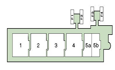
| Relay box #1 (Type 1: 2007-2012). | |
|
|
| 1 | Headlight washer pump relay |
| 2 | Coolant Heater Relay 1 (Diesel with Auxiliary Heater) |
| 3 | Coolant Heater Relay 2 (Diesel with Auxiliary Heater) |
| 4 | Starter relay |
| 5a | Fuel Pump Relay (Diesel) |
| 5b | Fuel pump relay (petrol engine, BSE/BSF) |
| F1 | Empty |
| F2 | Empty |
| F3 | Power seats 30A |
| F4 | Empty |
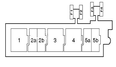
| Relay box #1 (Type 2: 2005-2006). | |
|
|
| 1 | Headlight washer pump relay |
| 2a | ^07/05 - Start Relay (Fuel System) (Petrol, BSE/BSF/BMJ/BUB) |
| 2b | Fuel pump relay (petrol engine, BSE/BSF) |
| 3 | →07/05: Starter relay |
| 4 | 08/05^ - Starter relay |
| 5a | 08/05^ - Start Relay (Fuel System) (Petrol, BSE/BSF/BMJ/BUB) |
| 5b | 08/05^ - Fuel Pump Relay (Petrol, BSE/BSF) |
| F1 | Empty |
| F2 | Empty |
| F3 | Power seats 30A |
| F4 | Empty |
| Relay box #1 (Type 3: 2002-2005). | |
|
|
| 1 | Headlight washer pump relay |
| 2a | Empty |
| 2b | Fuel Pump Relay (AZV/BKC/BKD) |
| 3a | Empty |
| 3b | Empty |
| 4 | training vehicle |
| 5 | training vehicle |
| F1 | Power windows, rear (5-door models) (30A) |
| F2 | Power windows, front (30A) |
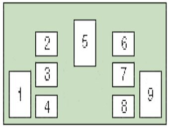
| Relay block #2 | |
|
|
| 1 | Relay 2 of the multifunction control unit |
| 2 | Seat heater relay |
| 3 | Empty |
| 4 | Relay 1 of the multifunction control unit |
| 5 | Rear defroster relay |
| 6 | Horn relay |
| 7 | Windshield/rear window washer pump relay 2 |
| 8 | Windshield/rear window washer pump relay 1 |
| 9 | Ignition Auxiliary Relay |
In the engine compartment
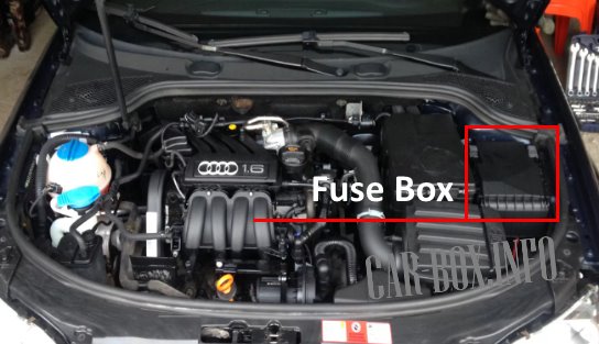
Located on the left side of the engine compartment, next to the battery.
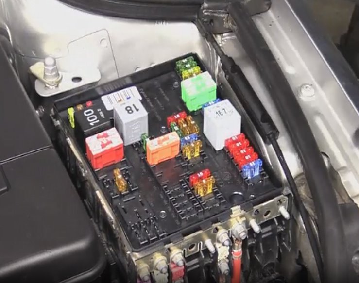
Fuse box
Access example.
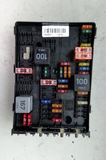
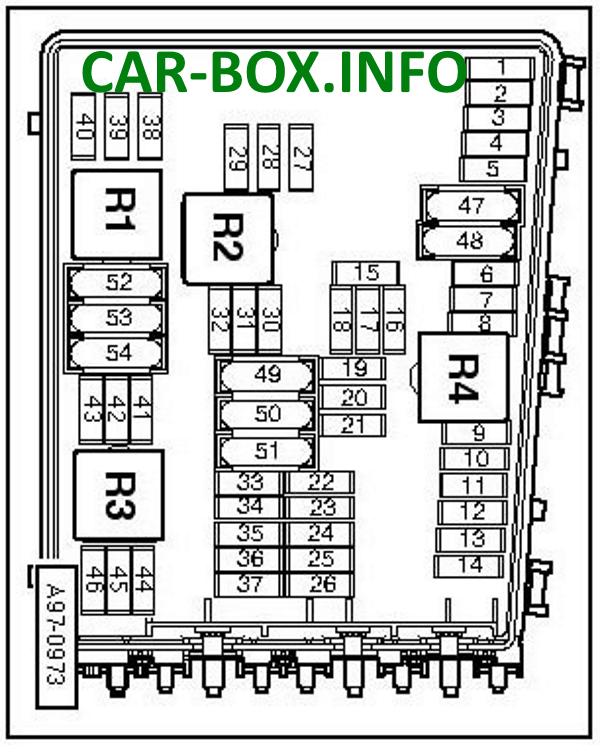
The main underhood block. There are four types of schema variations
| Assigment of fuses in the engine compartment | ||
|---|---|---|
| Execution #1 | ||
|
||
| Type #1 | ||
| No. | Purpose | A |
| F1 | Anti-Lock Braking System (ABS) | 30 |
| F2 | 30 | |
| F3 | ^2007: Multifunction control unit 2 | 20 |
| F4 | Multifunction control box 1 | 5 |
| F5 | Sound signal | 15 |
| F6 | Engine management | 15 |
| F7 | Empty | — |
| F8 | Empty | — |
| 9 | Engine management | 10 |
| 10 | 10 | |
| 11 | 10 | |
| 12 | 10 | |
| 13 | Transmission control system (automatic transmission) (manual transmission (DSG) | 15 |
| 14 | Empty | — |
| 15 | Coolant pump motor | 10 |
| 16 | Steering column electrical control unit | 5 |
| 17 | instrument cluster | 5 |
| 18 | Audio system | 30 |
| 19 | Audio system, navigation system | 15/25 |
| 20 | Navigation system, telephone | 5 |
| 21 | Empty | — |
| 22 | Empty | — |
| 23 | Engine management | 5/10 |
| 24 | Diagnostic block | 5 |
| 25 | Empty | — |
| 26 | Empty | — |
| 27 | Exhaust Control Valve (BHZ) | 5 |
| 28 | Engine management | 25 |
| 29 | Coolant Pump Relay, Exhaust Air Pump Relay | 5 |
| 30 | Additional heater | 20 |
| 31 | windshield wiper | 30 |
| 32 | Empty | — |
| 33 | Empty | — |
| 34 | Empty | — |
| 35 | Empty | — |
| 36 | Empty | — |
| 37 | Empty | — |
| 38 | Cooling fan motor control unit, engine management system | 10 |
| 39 | Stop Lamp Switch (Brake Pedal Position Sensor), Clutch Pedal Position Sensor | 5 |
| 40 | Engine management | 20 |
| 41 | Empty | — |
| 42 | Engine management | 5 |
| 43 | Engine management | 30 |
| 44 | Empty | — |
| 45 | Empty | — |
| 46 | Empty | — |
| 47 | Multifunction control box 1 | 30/40 |
| 48 | 30/40 | |
| 49 | ^2007: Dashboard Fuse/Relay Box, MFC Relay 2 | 40 |
| 50 | Empty | — |
| 51 | Engine management | 40 |
| 52 | ^2007: Instrument panel fuse/relay box, auxiliary circuit relay, multifunction control box 1. | 40/50 |
| 53 | ^2007 : Power Seats, Dashboard Fuse/Relay Box | 50 |
| 54 | Empty | — |
| R1 | Main Ignition Relay | |
| R2 | Coolant pump relay (AXX/ B HZ/BMJ/ B PY/ B UB/BWA) | |
| R3 | Empty | |
| R4 | Fuel Pump Relay (BMJ/BUB) | |
| Type #2 | ||
| 1 | Anti-Lock Braking System (ABS) | 30 |
| 2 | 30 | |
| 3 | Multifunctional control box2 | 2 |
| 4 | Multifunction control unit 1- except 3.2 (BDB) | 5 |
| 5 | Sound signal | 20 |
| 6 | Engine Management System - Gasoline | 5/20/30 |
| 7 | Stop Lamp Switch (Brake Pedal Position Sensor) | 5 |
| 8 | Cooling fan motor control unit, engine management system | 10 |
| 9 | Engine management | 10 |
| 10 | 10 | |
| 11 | Engine management system - petrol | 25 |
| 12 | Engine management | 15 |
| 13 | Automatic transmission | 20 |
| 14 | Empty | — |
| 15 | Starter | 40 |
| 16 | Steering column electrical control unit | 15 |
| 17 | instrument cluster | 10 |
| 18 | Audio system | 30 |
| 19 | Audio system, navigation system | 15 |
| 20 | Telephone | 5 |
| 21 | Navigation system | 10 |
| 22 | Empty | — |
| 23 | Empty | — |
| 24 | Diagnostic unit, ignition switch | 10 |
| 25 | Empty | — |
| 26 | Engine Management System - Diesel | 5 |
| 27 | Crankcase ventilation heater | 10 |
| 28 | automatic transmission | 20 |
| 29 | Engine management | 10/20 |
| 30 | Additional heater | 20 |
| 31 | windshield wiper | 25 |
| 32 | Engine management | 10 |
| 33 | Fuel pump | 15 |
| 34 | Empty | — |
| 35 | Empty | — |
| 36 | Empty | — |
| 37 | Empty | — |
| 38 | Headlights corrector | 10 |
| 39 | Engine oil temperature sensor, instrument cluster | 5 |
| 40 | Fuse/Relay Box 1 Dashboard | 30 |
| 41 | Empty | — |
| 42 | Engine Management System - Gasoline | 5 |
| 43 | Vacuum pump for brake booster | 20 |
| 44 | Engine Management System - Diesel | |
| 45 | Engine management | 10/15 |
| 46 | 10 | |
| 47 | Multifunction control box 1 | 40 |
| 48 | 40 | |
| 49 | Relay 2 of the multifunction control unit | 30 |
| 50 | Empty | — |
| 51 | Engine management system - petrol | 40 |
| 52 | Multifunction control box 1 | 50 |
| 53 | Dashboard Fuse/Relay Box 1 (F32-F37) - Except 3.2(BDB) | 50 |
| 54 | Cooling fan motor control unit | 50 |
| R1 | Relay 2 main ignition circuits | |
| R2 | Starter relay | |
| R3 | Fuel pump relay-1.6(BGU)/3.2(BDB) | |
| R4 | Relay 1 Main Ignition Circuits | |
| Type #3 | ||
| 1 | Anti-Lock Braking System (ABS) | 30 |
| 2 | 30 | |
| 3 | Multifunction control box 2 | 20 |
| 4 | Multifunction control unit 1 (except BDB/BMJ) | 5 |
| 5 | Sound signal | 20 |
| 6 | Engine management | 15/20/30 |
| 7 | Stop Lamp Switch (Brake Pedal Position Sensor), Clutch Pedal Position Sensor | 5 |
| 8 | Cooling fan motor control unit, engine management system | 10 |
| 9 | Coolant pump motor (if equipped), engine management system | 10 |
| 10 | Engine management | 10 |
| 11 | engine management system petrol) | 25 |
| 12 | Engine management | 15 |
| 13 | Transmission control system (automatic transmission) (manual transmission (DSG) | 20 |
| 14 | Empty | — |
| 15 | Starter | 40 |
| 16 | Steering column electrical control unit | 15 |
| 17 | instrument cluster | 10 |
| 18 | Audio system | 30 |
| 19 | Audio system, navigation system | 15 |
| 20 | Telephone | 5 |
| 21 | Navigation system | 10 |
| 22 | Empty | — |
| 23 | Empty | — |
| 24 | Diagnostic block | 10 |
| 25 | Empty | — |
| 26 | Engine management | 5/10 |
| 27 | Crankcase ventilation heater | 5/10 |
| 28 | Automatic transmission | 20 |
| 29 | Engine management | 10/20 |
| 30 | Additional heater | 20 |
| 31 | windshield wiper | 30 |
| 32 | Engine management | 10 |
| 33 | 15 | |
| 34 | Empty | — |
| 35 | Empty | — |
| 36 | Empty | — |
| 37 | Empty | — |
| 38 | Headlights corrector | 10 |
| 39 | Engine Oil Condition Sensor | 5 |
| 40 | Dashboard Fuse/Relay Box 1 (F1-F11/F29-F31) (Except BDB/BMJ) | 20/30 |
| 41 | Engine management | 10 |
| 42 | 5/10 | |
| 43 | Brake booster vacuum pump (if equipped) | 20 |
| 44 | Engine management | 10 |
| 45 | 10/15 | |
| 46 | 10 | |
| 47 | Multifunction control box 1 | 40 |
| 48 | 40 | |
| 49 | Passenger compartment fuse/relay box 1 (F1-F11/F29-F31) - (BDB/BMJ), MFC relay 2 | 30 |
| 50 | Empty | — |
| 51 | Engine management | 40 |
| 52 | Interior fuse and relay box, auxiliary circuit relay, multifunction control box 1. | 50 |
| 53 | Dashboard Fuse/Relay Box 1 (F32-F37)-(BDB/BMJ) | 50 |
| 54 | Cooling fan motor control unit | 50 |
| R1 | Relay 2 main ignition circuits | |
| R2 | Starter relay | |
| R3 | Fuel Pump Relay (BDB/BGU/BMJ) | |
| R4 | Relay 1 Main Ignition Circuits | |
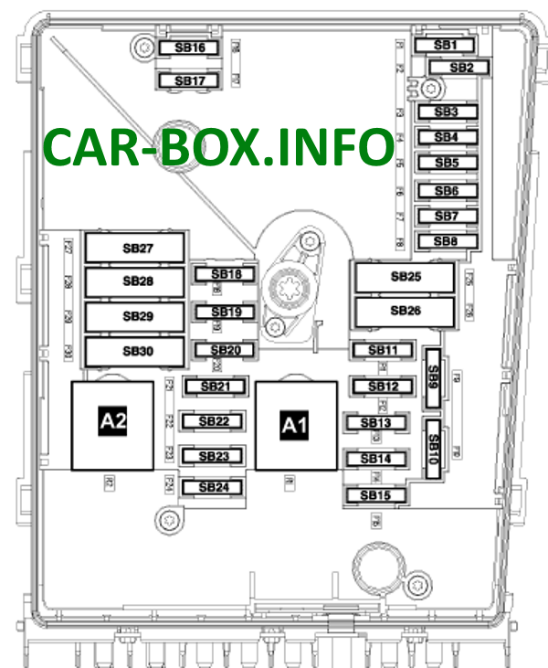
| Execution #2 | ||
|
||
|
||
| No. | Purpose | A |
| SB1 | ^2007: Multifunction control unit 2 | 20 |
| SB2 | Steering column electrical control unit | 5 |
| SB3 | Multifunction control box 1 | 5 |
| SB4 | Anti-Lock Braking System (ABS) | 30 |
| SB5 | Transmission control system (automatic transmission) (manual transmission (DSG) | 15 |
| SB6 | Instrument cluster control unit | 5 |
| SB7 | Empty | |
| SB8 | Audio system, navigation system | 15/25 |
| SB9 | Navigation system, telephone | 5 |
| SB10 | Engine management | 5/10 |
| SB11 | Additional heater | 20 |
| SB12 | Diagnostic block | 5 |
| SB13 | Engine management | 25/30 |
| SB14 | 20 | |
| SB15 | 5/10 | |
| SB16 | Anti-Lock Braking System (ABS) | 30 |
| SB17 | Sound signal | 15 |
| SB18 | Audio system | 30 |
| SB19 | windshield wiper | 30 |
| SB20 | E/m the valve of management of a regulator of pressure of fuel (BPT/BPU/BYT) | 20 |
| SB21 | Engine management | 10/15 |
| SB22 | Stop Lamp Switch (Brake Pedal Position Sensor), Clutch Pedal Position Sensor | 5 |
| SB23 | Coolant pump relay, engine management system | 5/10 |
| SB24 | Cooling fan motor control unit (some models), engine management system | 10 |
| SB25 | Multifunction control box 1 | 30/40 |
| SB26 | 30/40 | |
| SB27 | Exhaust Air Supply Pump (BSE) | 40 |
| SB28 | ^2007 : Instrument Panel Fuse/Relay Box, Relay 2, MFC | 40 |
| SB29 | ^2007 : Power Seats, Dashboard Fuse/Relay Box | 50 |
| SB30 | ^2007 : Instrument panel fuse/relay box 1, auxiliary circuit relay, multifunction control box 1. | 40/50 |
| A1 | Main Ignition Relay | |
| A2 | Exhaust Air Pump Relay(BSE) | |
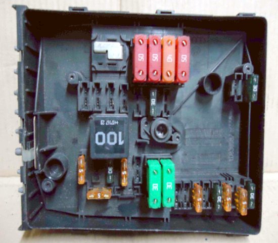
Additional relay box
Only cars with diesel engines.
|
|
| No. | Purpose |
| 1 | Spare |
| 2 | glow plugs |
| 3 | Spare |
| 4 | |
| 5 | outlet air supply |
| 6 | coolant pump |
Power fuses
Located on the battery.
|
||
| No. | Purpose | A |
| Type 1 | ||
| F1 | Generator | 150/200 |
| F2 | power steering | 80 |
| F3 | Cooling fan motor | 80 |
| F4 | Passenger compartment fuse/relay box 1, passenger compartment fuse/relay box 2 - BDB | 80 |
| F5 | Additional heater | 100 |
| F6 | Fuse and relay box 1 in the cabin (F12-F17 / F44-F45) -3.2 (BDB) | 50 |
| F7 | Empty | — |
| Type 2 | ||
| F1 | Generator | 150/200 |
| F2 | power steering | 80 |
| F3 | Cooling fan motor control unit | 50 |
| F4 | ^10/05 - Passenger compartment fuse/relay box | 80 |
| F5 | 11/05-07: Interior Fuse/Relay Box | 80 |
| F6 | Empty | — |
| F7 | Service vehicles | 50/80 |
