- Location of all units
- Main fuses -A- on the battery
- Unit -TV1- (hybrid engines; in the trunk)
- Assembly -TV67- (hybrid engines; in trunk)
- Fuse box 2 -SR2- (holder -SF-; in the trunk)
- Fuse box C -SC- (in the passenger compartment)
- Fuse box 1 -SR1- (-SB- holder; in the passenger compartment)
- Unit 4 -SR4- (in the passenger compartment)
- Unit 3 -SR3- (in engine compartment)
- Unit 5 -SR5- (in the engine compartment)
- Unit A -SA- (in the engine compartment)
- Assembly -TV66- (Hybrid motors; in engine compartment)
Audi A4 (B9) is the fifth generation of a mid-size sedan and station wagon from the German manufacturer. The official premiere took place in September 2015 at the International Motor Show. In this material we will analyze in detail the fuse box diagrams of Audi A4 B9 (fifth generation; MLB Evo platform; body brand W8) 2015, 2016, 2017, 2018, 2019, 2020, 2021, 2022, 2023, 2024 model years.

Here you will find the locations and photos of distribution boxes. The fuses responsible for the “Cigarette lighter” and “Fuel Pump” are highlighted in bold.
Location of all units

General location of electronic modules:
1. Relay and fuse box 2 -SR2-
2. Assembly -TV1- (for models with 48-volt hybrid system)
3. Main fuse block on battery -A- (not for CNG engine models)
4. Node 2 for terminal 40 -TV67- (for models with 48-volt hybrid system)
5. Fuse box C -SC- (at the end of the instrument panel)
6. Relay and fuse box 1 -SR1- with fuse holder B -SB-
7. Main fuse box on battery -A- (CNG engine models only)
8. Relay and fuse box 3 -SR3- / relay and fuse holder 5 -SR5-
9. Relay and fuse box 4 -SR4-
10. Terminal connector 40 -TV66- (for models with 48-volt hybrid system)
11. fuse box A -SA-
Main fuses -A- on the battery
The installation location differs depending on the type of engine installed
All engines (except CNG)
Located in the trunk on the battery.

A. | To fuse and relay box 2 -SR2- (holder -SF-) | 80A
B. | To power steering control unit -J500- | 125A
C. | To the plus terminal B302 6(30) in the main wiring harness | 150A
D. | To B272 positive connection (30) in the main wiring harness and to B298 positive connection 2 (30) in the main wiring harness | 200A
With CNG engine

Description:
A. | to power steering control unit -J500- | 125A
B. | Power supply for terminal 30 of splitter 3 wiring harness -TV28- | 300A
C. | not assigned
D. | Power supply for windshield heater -Z2- | 70A
E. | Power supply for block 1 -SR1- (holder -SB-) | 200A
F. | Power supply unit 2 -SR2- (holder -SF-) | 150A
Unit -TV1- (hybrid engines; in the trunk)
Installed on vehicles with 48-volt hybrid system.

A. | Fuse 4 on the -S374- connector to the voltage converter, 48V/12V -A7- | 300A.
B. | not assigned
C. | Fuse 2 on assembly unit -S372- , to block 2 -SR2- | 70A
D. | not assigned
E. | Connection to terminal 30, from the fuses in the -S- holder.
Assembly -TV67- (hybrid engines; in trunk)
Installed on vehicles with 48-volt hybrid system.

A. | Connect terminal 40 from -TV66-. terminal 40.
B. | Connect terminal 40 to the battery, 48 V -A6-.
C. | Fuse 1 on mounting unit 2 for terminal 40 -S368-, to voltage converter, 48 V/12 V -A7- | 125A
D. | Not assigned
E. | not assigned
Fuse box 2 -SR2- (holder -SF-; in the trunk)

This fuse box is located in the left side of the luggage compartment. To access it, a part of the trim must be removed.

Example of access.

General view.
| Diagram | ||
|---|---|---|

|
||
| No. | Description | Amps |
| R1 | Right side windshield heater relay -J411- | |
| R1 | Two-way radio voltage relay 2 -J888- *for special vehicles only* | |
| R2 | Two-way radio voltage relay -J84- *for special vehicles only* | |
| R3 | Two-way radio voltage relay -J84- *for special vehicles only* | |
| R4.1 | Left side windshield heater relay -J410- | |
| R4.2 | Right side windshield heater relay -J411- | |
| R5 | Digital sound package fuse -S358- 40A (From July 2019) | 40A |
| A | Heated rear window fuse -S41- , 40A | 40A |
| A | Automatic transmission control unit fuse -S113- *not for natural gas vehicles* | 50A |
| B | Heater element fuse 1 -S291- | 15A |
| C | Front passenger seat adjustment thermal fuse 1 -S46- | 15A |
| D | Terminal 30 fuse, trailer tow hitch -S77- *only for Australian models and US equipped models only* | 30A |
| ST1 panel, black | ||
| 1 | Empty | - |
| 2 | Right side windshield heater relay -J411- and Windshield heater -Z2-. | 35A |
| 3 | Left side windshield heater relay -J410- and Windshield heater -Z2-. | 35A |
| 4 | Empty | - |
| 5 | Chassis Control Unit -J775 | 15A |
| 6 | Automatic transmission control unit -J217- 6) and Selector lever -E313- 2) | 15A 6) / 7.5A 2) |
| 7 | Rear window heater relay -J9- 3) | 30A |
| 8 | Control and display unit for the rear air conditioning system -E265 | 30A |
| 9 | Central comfort control unit -J393- 4); Power supply: rear left lamps -MX3- | 20A |
| 10 | Front left front seat belt tensioner control unit -J854- | 25A |
| 11 | Comfort system central control unit -J393- 5); Power: rear center lamp and left rear lamp 2 -MX5-, Right rear lamp 2 -MX6- | 20A |
| 12 | Rear cover control unit -J605 | 30A |
| Note: 1) Depending on equipment 2) For gas engine models 3) Avant models only 4) (T17a/16), 5) (T17a/17), 6) Not for natural gas vehicles | ||
| ST3 panel, brown | ||
| 1 | Empty | |
| 2 | Aerodynamic amplifier for mobile phone -R86- | 5A |
| 3 | Front passenger multi-contour seat control unit -J872-, Front right seat lumbar support adjustment switch -E753-, Front passenger seat lumbar support longitudinal adjustment motor -V126-. Front passenger seat lumbar support height adjustment motor -V130-. | 7,5A |
| 4 | Lane change assist control unit | 5A |
| 5 | Control unit for the rear information displays and control panels | 10A |
| 6 | Tyre pressure monitoring system control unit -J502- | 5A |
| 7 | Short-range communication control unit 2 -J1170-, Short-range communication control unit -J1169- | 5A |
| 8 | Auxiliary heater remote control receiver -R64-, Dosing pump -V54-, Fuel tank leak detection control unit -J909- | 5A |
| 9 | Empty | |
| 10 | TV tuner -R78- | 5A |
| 11 | 48 V battery -A6-, Second battery -A1-, Connection point in the passenger compartment -TI- (/3) | 10A |
| 12 | Garage door operation control unit -J530-, Garage door control unit -E284- | 5A |
| 13 | Reverse camera system control unit -J772-, Top view camera control unit -J928- | 5A |
| 14 | Convenience system central control unit -J393-, (T17b/16) Power supply: Right tail lamp -MX4- | 20A |
| 15 | Empty | |
| 16 | Front right front seatbelt tensioner control unit | 25A |
| ST5 panel, red | ||
| 1 | Empty | |
| 2 | Digital Sound Pack Control Unit -J525- | 30A |
| 3 | Reducer dosing system control unit -J880- | 30A |
| 4 | Empty | |
| 5 | Trailer detector control unit -J345- | 25A |
| 6 | Empty | |
| 7 | Trailer Detector Control Unit -J345- | 15A 1) / 20A 2) |
| 8 | Trailer Detector Control Unit -J345- | 25A |
| 9 | Trailer Detector Control Unit -J345- | 15A 1) / 20A 2) |
| 10 | Differential lock control unit -J187 | 40A |
| 11 | Restorer metering system control unit -J880- | 25A |
| 12 | Empty | |
| Panel ST6, black | ||
| 1 | Positive connection 8 (30a) in the vehicle's dedicated wiring harness -X227- | 5A |
| 2 | 12V outlet -U5- | 15A |
| 3 | 12V outlet #2 -U18- | 15A |
| 4 | 12V outlet #3 -U19- | 15A |
| 5 | Two-way radio voltage relay -J84- | 10A |
| 6 | Two-way radio voltage relay -J84- | 10A |
| 7 | Two-way radio voltage relay #2 -J888- | 10A |
| 8 | Two-way radio voltage relay 2 -J888- | 10A |
| 9 | Positive connector 4 (30a) in the special vehicle wiring harness -X223- | 5A |
| 10 | Positive terminal 2 (58) in the special vehicle wiring harness -A251- | 10A |
| 11 | Connection point in the luggage compartment, center -THRM- pin 16. | 5A |
| 12 | Positive contact 3 (30a) in special vehicle wiring harness -X222- | 7,5A |
| 13 | Special vehicle control unit -J608- , pin 18 | 1A |
| 14 | Empty | |
| 15 | Connection point in the luggage compartment (right -THRR-), Turn signal light and horn control unit -J23- , pin 18 Blank | 20A |
| 16 | Empty | |
Fuse box C -SC- (in the passenger compartment)
Located in the end of the instrument panel on the driver's side.

General view.
| Diagram | ||
|---|---|---|

|
||
| No. | Description | Amps |
| 1 | Empty | - |
| 2 | Chip card reader control unit -J676-, Phone bracket -R126- | 5A |
| 3 | Empty | - |
| 4 | Head-Up Display Control Unit -J898-, Phone Bracket -R126- Empty | 5A |
| 5 | Connector for connecting external audio sources -R199- | 5A |
| 6 | Front air conditioning control and display unit -E87-, Heater control unit -J65- | 10A |
| 7 | Control unit for electronic steering column lock -J764- | 10A |
| 8 | Indicator unit for front information display and control unit for the control panel -J685- | 10A 3) / 5A 3) |
| 9 | Control unit in the instrument panel insert -J285- | 10A |
| 10 | Multimedia system control unit -E380- | 5A |
| 11 | Light switch -E1-, Control unit 1 for driving and comfort functions -E791- | 5A |
| 12 | Steering column electronics control unit -J527- | 1A |
| 13 | Empty | - |
| 14 | Control unit 1 for information electronics -J794- | 20A 1) / 5A 2) |
| 15 | Empty | |
| 16 | Steering column electronics control unit -J527-, Heated steering wheel -Z36- | 10A |
| Note: 1) 8RM sound system, 2) 9VS and 8RF sound system, 3) According to the equipment | ||
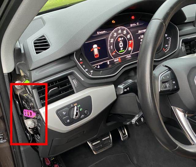
Fuse box 1 -SR1- (-SB- holder; in the passenger compartment)

Located in the lower part of the instrument panel, in the driver's footwell. The assignment of the fuses in the panel may vary depending on the engine installed. Only left-hand drive models are considered.

General view.
| Diagram | ||
|---|---|---|

|
||
| No. | Description | Amps |
| A | ABS Control Unit 1 -S123- and ABS Control Unit 2 -S124- | 40A |
| B | Automatic transmission control unit fuse -S113- (For natural gas engine models) | 50A |
| C | Driver's seat adjustment thermal fuse 1 -S44- | 15A |
| Panel ST1, brown (diesel engines) | ||
| 1 | Empty | |
| 2 | Exhaust cam drive 1 for cylinders 1-6 1) | 15 |
| 3 | Radiator shutter control motor -V544- 2); Radiator louvre control motor 2 -V550- 2) | 5 |
| 4 | NOx sensor control unit -GX30-, NOx sensor control unit -G295-, NOx sensor control unit -J583-, NOx sensor control unit 2 -GX46-, NOx sensor 2 -G687-, NOx sensor control unit 2 -J881-, biodiesel concentration sensor -G855- 7), Particulate matter sensor -G784- 3), NOx sensor control unit 2 -J881- 3), Coolant circulation pump -V50- | 5A 2) / 10A 3) / 15A 9) |
| 5 | Brake light switch -F- | 5 |
| 6 | Supercharger pressure control solenoid valve -N75- 2), Oil pressure control valve -N428- 2), Cylinder head coolant valve -N489-, Left engine mount electrohydraulic solenoid valve -N144- 2), Right engine mount electrohydraulic solenoid valve -N145- 2), Automatic glow period control unit -J179- 3), Engine cooling system thermostat with map control -F265- 4), Camshaft adjustment actuator 1 -F366- 8), Camshaft adjustment actuator 2 -F367- 8), Coolant circulation pump -V50- 1), Exhaust gas recirculation system cooler switching valve -N345- 3) 5), Oil pressure control valve -N428- 9), Piston cooling jet control valve -N522- 9) | 10A 1) 9) 3) / 5A 2) / 7.5A 4) |
| 7 | Air mass meter -G70-, Engine control unit -J623- 3), Crankcase breather heater -N79- 2), Coolant switch valve 2 -N633- 9), Charge air cooling pump -V188- 9) | 5A 2) 3) / 10A 9) |
| 8 | Fuel pressure regulating valve -N276-, Fuel dosing valve -N290-, Coolant circulation pump -V50-, Radiator louvre control motor -V544- | 10A |
| 9 | Engine component energising relay -J757-, Starter-alternator -C29- 8), Starter-alternator coolant pump -V621- 8), Electric compressor control unit -J1123- 8) | 5A |
| 10 | Oil level and temperature sensor -G266-, Crankcase breather heater -N79- 9) | 5A |
| 11 | Clutch position sensor -G476-, Alternator starter -C29- 9) | 5A |
| 12 | Camshaft adjustment actuator 1 -F366-, Camshaft adjustment actuator 2 -F367-, Air filter bypass valve flap -N275-, Charge air temperature sensor upstream of charge air cooler -G810- 1), Coolant circulation pump -V50- 4), Left engine mount electrohydraulic solenoid valve -N144- 3), Right engine mount electrohydraulic solenoid valve -N145- 3), Auxiliary heating pump -V488- 2), Automatic light period control unit -J179- 2), Charge air cooler pump -V188- 2) | 5A / 9) 7.5A 3) / 10A 2) |
| 13 | Radiator fan -VX57-, Radiator fan control unit -J293-, Radiator fan control unit 2 -J671- 6) | 5A |
| 14 | Engine Control Unit -J623- | 15A |
| 15 | Lambda probe 1 before catalytic converter -GX10-, Lambda probe heater -Z19- | 10A |
| 16 | Fuel pump control unit -J538- | 25A 2) / 30 A3) |
| Note: 1) Only DCPC, DCPE 2) Only models with 4-cylinder engine 3) Only models with 6-cylinder engine 4) Only CRTC, DCPC, DCPE 5) Only for US markets 6) Only models with hitch 7) Only models with Euro 5 plus (7MJ) 8) Only DEWA, DEWB 9) Only DEZB, DEZE | ||
| ST1 panel, brown (models with 4-cylinder petrol engine) | ||
| 1 | Empty | - |
| 2 | Empty | - |
| 3 | Empty | - |
| 4 | Circulation pump -V55- 2), Continuous coolant circulation pump -V51- 3) | 5A |
| 5 | Brake light switch -F- | 5A |
| 6 | Actuators 1 - 8 for camshaft adjustment 4) 5), Piston cooling jet control valve -N522- | 15A |
| 7 | Lambda probe 1 after catalytic converter -GX7- 1) 4) 5), Lambda probe 1 before catalytic converter -GX10- 1) | 15A |
| 8 | Left engine mount electro-hydraulic solenoid valve -N144- 7), Charge air cooling pump -V188- 1), Right engine mount electro-hydraulic solenoid valve -N145- 2) 7), Coolant circulation pump -V50- 2), Charge air cooling pump -V188- | 15A 1) / 5A 2) |
| 9 | Circulation pump -V55- 1), Engine component current relay -J757- 2) | 5A |
| 10 | Oil level and temperature sensor -G266- | 5A |
| 11 | Clutch position sensor -G476-, Starter-generator -C29- 8) | 5A |
| 12 | Carbon filter solenoid valve 1 -N80-, Intake secondary air valve -N112- 5), Camshaft control valve 1 -N205-, Turbocharger air recirculation valve -N249- 2), Intake manifold damper valve -N316- 3) 4) 5), Exhaust camshaft control valve 1 -N318-, Oil pressure control valve -N428-, Piston cooling jet control valve -N522- 2), Camshaft adjustment actuators 1 - 8 3) 6) | 15A 1) / 10A 2) |
| 13 | Radiator fan -VX57- | 5A |
| 14 | Engine control unit -J623-, Injector 2 for cylinder 1 -N532- 3) 4), Injector 2 for cylinder 2 -N533- 3) 4), Injector 2 for cylinder 3 -N534- 3) 4), Injector 2 for cylinder 4 -N535- 3) 4) | 15A |
| 15 | Lambda probe 1 before catalytic converter -GX10- 2), Lambda probe 1 after catalytic converter -GX7- 3) 6), Ignition coil 1 with output stage -N70- 1), Ignition coil 2 with output stage -N127- 1), Ignition coil 3 with output stage -N291- 1), Ignition coil 4 with output stage -N292- 1) | 20A 1) / 15A 2) |
| 16 | Fuel pump control unit -J538-, petrol pump fuse Audi A4 B9 | 25A |
| Note: 1) only with 1.4 litre petrol engine 2) only with 2.0 litre petrol engine 3) CVKB 4) CYRB, CYRC 5) CYMC 6) DBPC 7) automatic transmission only | ||
| ST1 panel, brown (models with 6-cylinder petrol engine) | ||
| 1 | Empty | |
| 2 | Empty | |
| 3 | Empty | |
| 4 | Exhaust gas flap control unit -J883-, Exhaust gas flap control unit 2 -J945- | 7,5A |
| 5 | Brake light switch -F | 5A |
| 6 | Left and right engine mount electrohydraulic solenoid valve -N144- and -N145-, Carbon filter solenoid valve 1 -N80-, Excess air recirculation valve for can 1 -N625-, Inlet cam drive 1 for cylinder 1 -F448-, Inlet cam drive 1 for cylinder 2 -F452-, Inlet cam drive 1 for cylinder 3 -F456-, Inlet cam drive 1 for cylinder 4 -F460- | 10A |
| 7 | Lambda probe 1 after catalytic converter -GX7- | 15A |
| 8 | Inlet cam drive 1 for cylinder 5 -F464-, Inlet cam drive 1 for cylinder 6 -F468-, Engine cooling system thermostat with card control -F265- | 15A |
| 9 | Engine component energising relay -J757- | 5A |
| 10 | Oil level and temperature sensor -G266- | 5A |
| 11 | Empty | |
| 12 | Supercharger pressure control solenoid valve -N75-, Camshaft control valve 1 -N205-, Camshaft control valve 2 -N208-, Exhaust camshaft control valve 1 -N318-, Exhaust camshaft control valve 2 -N319- | 15A |
| 13 | Radiator fan -VX57- | 5A |
| 14 | Engine control unit -J623- | 15A |
| 15 | Lambda probe 1 before catalytic converter -GX10- | 15A |
| 16 | Fuel pump control unit -J538-, petrol pump fuse | 30A |
| ST1 panel, brown (cars with 2.0 litre CNG engine) | ||
| 1 | Empty | |
| 2 | Empty | |
| 3 | Empty | |
| 4 | Circulation pump -V55- | 5A |
| 5 | Stop lamp switch -F- | 5A |
| 6 | Empty | |
| 7 | Empty | |
| 8 | Left engine mount electrohydraulic solenoid valve -N144-, Right engine mount electrohydraulic solenoid valve -N145-, Coolant circulation pump -V50-, Radiator louver control motor -V544- | 7,5A |
| 9 | Engine component energising relay -J757- | 5A |
| 10 | Oil level and temperature sensor -G266- | 5A |
| 11 | Empty | |
| 12 | Carbon filter solenoid valve 1 -N80-, Camshaft control valve 1 -N205-, Turbocharger air recirculation valve -N249-, Intake manifold flap valve -N316-, Exhaust camshaft control valve 1 -N318-, Oil pressure control valve -N428-, Piston cooling jet control valve -N522-, Actuator 1 for camshaft adjustment -F366-, Actuator 2 for camshaft adjustment F366-, Drive 2 for camshaft adjustment -F367-, Drive 3 for camshaft adjustment -F368-, Drive 4 for camshaft adjustment -F369-, Drive 5 for camshaft adjustment -F370-, Drive 6 for camshaft adjustment -F371-, Drive 7 for camshaft adjustment -F372-, Drive 8 for camshaft adjustment -F373-. | 15A |
| 13 | Radiator fan -VX57- | 5A |
| 14 | Engine control unit -J623-, Gas injection valves 1-2-3-4 | 15A |
| 15 | Lambda probe 1 before catalytic converter -GX10-, Lambda probe 1 after catalytic converter -GX7- | 15A |
| 16 | Fuel pump control unit -J538-, petrol pump fuse | 25A |
| Panel ST2, red | ||
| 1 | Anti-theft alarm sensor -G578-, Alarm signal -H12- | 5A |
| 2 | Main relay -J271-, Engine control unit -J623- | 5A |
| 3 | Front left front seat lumbar support adjustment switch -E752-, Driver's seat lumbar support longitudinal adjustment motor -V125-, Driver's seat lumbar support height adjustment motor -V129- | 7,5A |
| 4 | Selector lever -E313- | 7,5A |
| 5 | On-board power control unit -J519-, (T73b/12) Power supply: High-frequency horn -H2- and Low-frequency horn -H7- | 15A |
| 6 | Electromechanical parking brake button -E538- | 5A |
| 7 | Diagnostic data bus interface -J533- | 5A 1) / 10A 2) |
| 8 | Roof electronics control unit -J528-, Front roof module -WX3- | 5A |
| 9 | Airbag control unit -J234- | 5A |
| 10 | Empty | |
| 11 | ABS Control Unit -J104- | 5A |
| 12 | Temperature and light sensor -G397-, Light sensor -G399-, Diagnostic connector -U31- | 10A |
| 13 | On-board power control unit -J519-, (T73a/2) Power: air conditioner: Air conditioning magnetic clutch -N25-, Air conditioner compressor control valve -N280- | 20A |
| 14 | Front passenger door control unit -J387- | 20A |
| 15 | On-board power control unit -J519-, (T73a/12) Power: Interior lighting: Rear interior lamp -WX2- Front roof module -WX3- | 20A |
| 16 | Empty | |
| Note: 1) until May 2016; 2) since June 2016 | ||
| Panel ST3, black | ||
| 1 | On-board power control unit -J519-, (T73b/73) Power: Heated seats, Heated rear left seat cushion -Z10-, Heated rear left seat backrest -Z11-, Heated rear right seat cushion -Z12-, Heated rear right seat backrest -Z13-, Heated front left seat cushion -Z45-, Heated front right seat cushion -Z46-, Heated front left seat backrest -Z116-, Heated front right seat backrest -Z117-. | 30A |
| 2 | Wiper motor control unit -J400- | 30A |
| 3 | On-board power control unit -J519-, (T73a/66) Power supply: front left headlamps, Front left headlamp -MX1- | 30A |
| 4 | Sliding sunroof adjustment control unit -J245- | 20A 1) / 30A 2) |
| 5 | Driver's door control unit -J386- | 20A |
| 6 | On-board power control unit -J519-, (T73a/73) Power supply: Cigarette lighter -U1- or 12V connector | 20A |
| 7 | Rear passenger side door control unit -J927- | 20A |
| 8 | Four-wheel drive control unit -J492- | 15A |
| 9 | On-board power control unit -J519-, (T73b/66) Power: Front right headlamps, Front right headlamp -MX2- | 30A |
| 10 | On-board control unit -J519-, (T73b/1) Power supply: Washer pump -V5-, Headlight washer pump -V11-, Left washer nozzle heater -Z20-, Right washer nozzle heater -Z21-. | 35A |
| 11 | Rear driver's side door control unit -J926- | 20A |
| 12 | Auxiliary heater control unit -J364- | 30A |
| Note: 1) sedan only; 2) not for sedan | ||
| ST4 panel, black | ||
| 1 | Diagnostic connection -U31-, High beam assist control unit -J844-, Seat and steering column adjustment control unit with memory -J136-, Rear air conditioning control and display unit -E265-, Windscreen heater relay -J47-, Left side windscreen heater relay -J410-, Right side windscreen heater relay -J411-. | 5A |
| 2 | Diagnostic data bus interface -J533-, On-board power control unit -J519-, (T73a/7) Power: Park Distance Control (PDC) system | 10A |
| 3 | Engine sound control unit -J869-, Engine sound generator control unit -J943- | 5A |
| 4 | Clutch position sensor -G476- | 5A |
| 5 | Starter Relay 1 -J906-, Starter Relay 2 -J907- | 5A |
| 6 | Empty | |
| 7 | USB charging socket 2 -U38- | 5A |
| 8 | Garage door control unit -E284- | 5A |
| 9 | Adaptive cruise control unit -J428-, Control unit 2 for adaptive cruise control -J850- | 10A |
| 10 | Driving school mode relay -J746-, Connection point on left A-pillar -TAL-, T4fh/4 | |
| 11 | Front camera for driver assistance systems -R242- | 7,5A |
| 12 | Front right headlamp -MX2- | 10A |
| 13 | Front left headlamp -MX1- | 10A |
| 14 | Rear window wiper motor -V12- | 20A |
| 15 | Empty | |
| 16 | Empty | |
| Panel ST5, red | ||
| 1 | Ignition coils (1, 2, 3, 4) with output stage 1) 2) | 20A |
| 2 | High pressure valve for gas mode -N372- 2), Fuel tank shut-off valves 2) | 10A |
| 3 | Empty | |
| 4 | Empty | |
| 5 | Empty | |
| 6 | Auxiliary hydraulic pump 1 for transmission oil -V475-. | 15A |
| 7 | Power supply for fuse box C -SC- | 40A |
| 8 | Fresh air fan control unit -J126- | 30A |
| 9 | Empty | |
| 10 | Active steering control unit -J792- | 40A |
| 11 | Starter relay 2 -J907-, Starter relay 1 -J906- / Starter -B- fuse (50) -S216- | 35A |
| 12 | Special vehicle control unit -J608-, T12o/10, T12o/12 Connection point on left A-pillar -TAL- , T4fh/1 | 10A |
| Note: 1) only with 2.0 litre petrol engine; 2) only with 2.0 litre CNG engine | ||
Relay modules in the unit:
|
||
Unit 4 -SR4- (in the passenger compartment)

Located near the pillar on the front passenger's side.

A. | Heating element fuse 2 -S277- | 70 A
B. | Heating element fuse 1 -S276- | 40 A
R1. | Low heating output relay -J359-
R2. | High heating output relay -J360-
Unit 3 -SR3- (in engine compartment)

Located near the windscreen, in the centre of the engine compartment.

Description:
R1.1 | not assigned
R1.2 | Fuse (50) -S216-, 5A, to engine-ECU -J623-.
R2. | Starter relay 1 -J906-
R3 | Starter relay 2 -J907-
Unit 5 -SR5- (in the engine compartment)

Located near the windscreen, in the centre of the engine compartment.

Description:
A. | fuse 1 in holder -S1-, 35A
B. | Fuse 2 in holder -S2-, 35A
R1. | Left side windscreen heater relay-J410-.
R2. | Right side windscreen heating relay-J411-
Unit A -SA- (in the engine compartment)

Description:
1 | | Fuse holder A -SA-.
2 | Interference suppression filter -C24-
A. | 50A, to radiator fan control unit 2 -J671- | 50A
B. | to radiator fan control unit -J293- | 50A / 70A (depending on equipment)
C. | diesel, to automatic glow period control unit -J179- | 80A (4-cylinder engine) / 125A (6-cylinder engine)
D. | Separate fuse for radiator fan -S42- | 50A (depending on equipment) / 70A (6-cylinder engine) *only for vehicles with petrol engine and radiator fan*.
Assembly -TV66- (Hybrid motors; in engine compartment)
Installed on vehicles with a 48-volt hybrid system.

A. | Connect terminal 40 to connector 2 -TV67- in the boot.
B. | Connect terminal 40 from the starter motor -C29-.
C. | Fuse 1 at terminal 40 -S366-, to the electric compressor control unit
-J1123- | 150 A
