
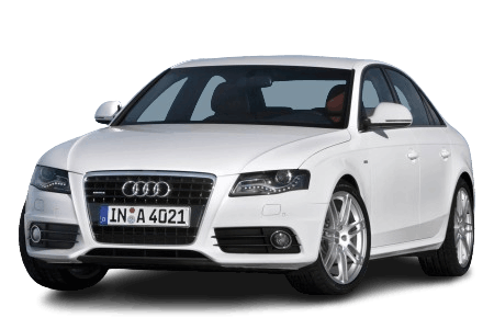
The Audi A4 (B8) is the fourth generation of the German automaker’s mid-size sedan and estate/wagon. This generation was produced from 2007 to 2015, with a facelift introduced in 2011. In this article, we provide a detailed overview of the fuse panel diagrams for the fourth-generation Audi A4 (B8): model years 2007, 2008, 2009, 2010, 2011, and 2012, 2013, 2014, 2015.
Here you will find fuse panel locations, photos, and assignment diagrams. The fuses for the “Cigarette Lighter” and “Fuel Pump” are highlighted in bold.
In the Luggage Compartment
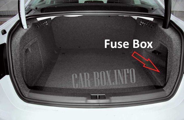
The fuse panel is located on the right side of the luggage compartment, behind the side trim panel.
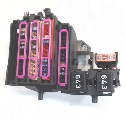
Overview.
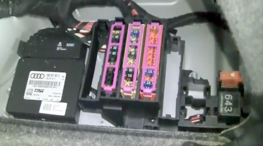
Access example.
| Diagram (2007–2011 Model Years) | ||
|---|---|---|

|
||
| 2007–2009 Models | ||
| No. | A | Function |
| Black fuse panel | ||
| 1 | — | — |
| 2 | 15 | Trailer control module |
| 3 | 20 | Trailer control module |
| 4 | 20 | Trailer control module |
| 5 | 5 | Electromechanical parking brake (EPB) |
| 6 | 15 | Adaptive damping control module |
| 7 | 30 | Electromechanical parking brake (EPB) |
| 8 | 30 | Onboard power supply control module 2 |
| 9 | — | — |
| 10 | 30 | Onboard power supply control module 2 |
| 11 | 20 | Onboard power supply control module 2 |
| 12 | — | — |
| Brown fuse panel | ||
| 1 | 15 | 12V socket |
| 2 | — | — |
| 3 | 7.5 | Radio / Navigation system |
| 4 | 30 | Digital Sound Package control module |
| 5 | 5 | MMI system |
| 6 | 30 | Driver door control module |
| 7 | 30 | Electromechanical parking brake (EPB) |
| 8 | 30 | Heated rear seats |
| 9 | 30 | Front passenger door control module |
| 10 | 5 | Auxiliary heater radio remote control receiver |
| 11 | 15 | Front passenger door control module |
| 12 | 5 | Rearview camera control module |
| Red fuse panel | ||
| 1 | 15 | Rear center console 12V socket |
| 2 | 15 | Front center console 12V socket |
| 3 | 15 | Luggage compartment 12V socket |
| 4 | 15 | Cigarette lighter fuse |
| 5 | 5 | Parking aid system |
| 6 | 5 | Cellular phone preparation (VDA interface) |
| 7 | 15 | Adaptive Cruise Control (ACC) control module |
| 8 | — | — |
| 9 | 5 | Electromechanical parking brake switch |
| 10 | 5 | Lane change assist (Audi side assist) |
| 11 | 5 | Heated rear seats |
| 12 | 5 | Airbag control module |
| 2010–2011 Models | ||
| No. | A | Function |
| Black fuse panel B | ||
| 1 | 30 | Tailgate control module (Avant) |
| 2 | 15 | Trailer control module |
| 3 | 20 | |
| 4 | 20 | |
| 5 | 5 | Electromechanical parking brake (EPB) |
| 6 | 15 | Adaptive damping control module |
| 7 | 30 | Electromechanical parking brake (EPB) |
| 8 | 30 | Onboard power supply control module 2 |
| 9 | 35 | Sport differential (quattro) |
| 10 | 30 | Onboard power supply control module 2 |
| 11 | 20 | Onboard power supply control module 2 |
| 12 | 5 | Terminal 30 |
| Brown fuse panel C | ||
| 1 | 30 | Tailgate control module |
| 2 | 15 | Heated front passenger seat |
| 3 | 40 | DC/DC converter (line 1) |
| 4 | 40 | DC/DC converter (line 2) |
| 5 | 30 | Diagnostic connector |
| 6 | — | — |
| 7 | 30 | Electromechanical parking brake (EPB) |
| 8 | 30 | Heated rear seats |
| 9 | 30 | Front passenger door control module |
| 10 | — | — |
| 11 | 15 | Front passenger door control module |
| 12 | — | — |
| Red fuse panel D | ||
| 1 | 15 | Rear center console 12V socket |
| 2 | 15 | Front center console 12V socket |
| 3 | 15 | Luggage compartment 12V socket |
| 4 | 15 | Cigarette lighter fuse |
| 5 | 5 | V6 FSI engine control |
| 6 | 5 | Rear Seat Entertainment power supply |
| 7 | 7.5 | Parking system control unit |
| 8 | 15 | Rear window wiper motor (Avant) |
| 9 | 5 | Electromechanical parking brake switch |
| 10 | 5 | Audi side assist |
| 11 | 5 | Heated rear seats |
| 12 | 5 | Terminal 15 control modules |
| Black fuse panel E | ||
| 1 | — | — |
| 2 | — | — |
| 3 | 30 20 |
DSP amplifier, radio |
| 4 | 7.5 | MMI system |
| 5 | 7.5 | Radio / Navigation / Cell phone preparation |
| 6 | 5 | Rearview camera |
| 7 | — | — |
| 8 | — | — |
| 9 | — | — |
| 10 | — | — |
| 11 | — | — |
| 12 | — | — |
| Diagram (2011–2015 Model Years) | ||
|---|---|---|
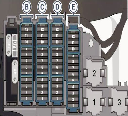
| 2011–2013 Models | ||
|
||
| No. | A | Function |
| Black fuse panel B | ||
| 1 | 30 | Tailgate control module (Avant) |
| 2 | 15 | Trailer control module |
| 3 | 20 | Trailer control module |
| 4 | 20 | Trailer control module |
| 5 | 5 | Electromechanical parking brake (EPB) |
| 6 | 15 | Adaptive damping control module |
| 7 | 30 | Electromechanical parking brake (EPB) |
| 8 | 30 | Onboard power supply control module 2 |
| 9 | 35 | Sport differential (quattro) |
| 10 | 30 | Onboard power supply control module 2 |
| 11 | 20 | Onboard power supply control module |
| 12 | 5 | Terminal 30 |
| Brown fuse panel C | ||
| 1 | 30 | Tailgate control module |
| 2 | 15 | Heated front passenger seat |
| 3 | 40 | DC/DC converter (line 1) |
| 4 | 40 | DC/DC converter (line 2) |
| 5 | 30 | Diagnostic connector |
| 6 | — | — |
| 7 | 30 | Electromechanical parking brake (EPB) |
| 8 | 30 | Heated rear seats |
| 9 | 30 | Front passenger door control module |
| 10 | — | — |
| 11 | 15 | Front passenger door control module |
| 12 | — | — |
| Red fuse panel D | ||
| 1 | 15 | Rear center console 12V socket |
| 2 | 15 | Front center console 12V socket |
| 3 | 15 | Luggage compartment 12V socket |
| 4 | 15 | Audi A4 (B8) cigarette lighter fuse |
| 5 | 5 | V6 FSI engine control |
| 6 | 5 | Rear Seat Entertainment power supply |
| 7 | 7.5 | Parking system control unit |
| 8 | 15 | Rear window wiper motor (Avant) |
| 9 | 5 | Electromechanical parking brake switch |
| 10 | 5 | Audi side assist |
| 11 | 5 | Heated rear seats |
| 12 | 5 | Terminal 15 control modules |
| Black fuse panel E | ||
| 1 | — | — |
| 2 | — | — |
| 3 | 30/20 | DSP amplifier, radio |
| 4 | 7.5 | MMI system |
| 5 | 7.5 | Radio / Navigation / Cell phone preparation |
| 6 | — | — |
| 7 | 5 | Cell phone preparation |
| 8 | — | — |
| 9 | — | — |
| 10 | — | — |
| 11 | — | — |
| 12 | — | — |
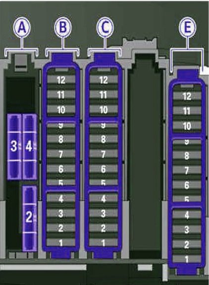
| 2014–2015 Models | ||
|
||
| No. | A | Function |
| Black fuse panel A | ||
| 1 | 30 | — |
| 2 | 30 | Heated rear window (Cabriolet) |
| 3 | 30 | Convertible top latching control (Cabriolet) |
| 4 | 50 | Convertible top electro-hydraulic drive (Cabriolet) |
| Black fuse panel B | ||
| 1 | 30/10 | Tailgate control module (Avant) / Convertible top control module (Cabriolet) |
| 2 | 10 | Retractable rear spoiler (RS 5 Coupé) |
| 3 | — | — |
| 4 | — | — |
| 5 | 5 | Electromechanical parking brake (EPB) |
| 6 | 15 | Adaptive damping control module |
| 7 | 30 | Electromechanical parking brake (EPB) |
| 8 | 30 | Rear exterior lighting |
| 9 | 35 | Sport differential (quattro) |
| 10 | 30 | Rear exterior lighting |
| 11 | 20 | Central locking system |
| 12 | 5 | Terminal 30 |
| Brown fuse panel C | ||
| 1 | 30 | Tailgate control module (allroad) |
| 2 | 20 | 12V socket, cigarette lighter fuse (Audi A4) |
| 3 | 40 | DC/DC converter (line 1) |
| 4 | 40 | DC/DC converter (line 2), DSP amplifier, radio |
| 5 | 30 | Head-level heating, right (Cabriolet) |
| 6 | — | — |
| 7 | 30 | Electromechanical parking brake (EPB) |
| 8 | — | — |
| 9 | 30 | Front passenger door (power window, central locking, door mirror, switches, lighting) |
| 10 | 30 | Head-level heating, left (Cabriolet) |
| 11 | 30 | 2-door: Right rear power window / 4-door: Right rear door (power window, central locking, switch, lighting) |
| 12 | 5 | Cell phone preparation |
| Black fuse panel E | ||
| 1 | 15 | Heated front passenger seat |
| 2 | — | — |
| 3 | — | — |
| 4 | 7.5 | MMI system |
| 5 | 5 | Radio |
| 6 | 5 | Rearview camera |
| 7 | 30 | Heated rear window (allroad) |
| 8 | 5 | Rear Seat Entertainment system |
| 9 | — | — |
| 10 | — | — |
| 11 | — | — |
| 12 | — | — |
In the Passenger Compartment
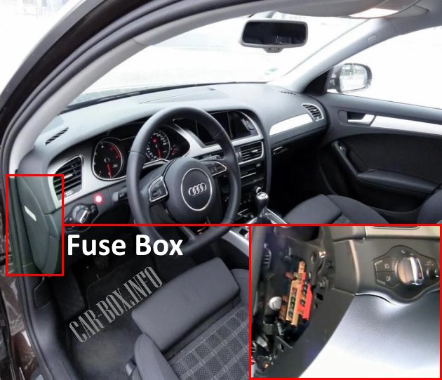
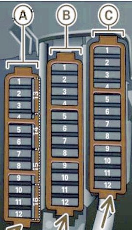
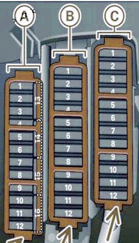
There are two fuse panels in the cabin: one on the driver’s side and the other on the front passenger side.
Driver’s Side Fuse Panel
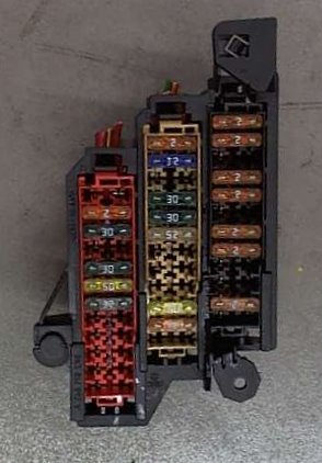
Example view of the driver’s side fuse panel.
| Fuse Assignment (2007–2011 Model Years) | ||
|---|---|---|
|
||
| 2007–2009 Models | ||
| No. | A | Function |
| Black fuse panel A | ||
| 1 | 5 | Dynamic steering |
| 2 | 5 | Clutch pedal position sensor |
| 3 | 5 | Garage door opener (HomeLink) |
| 4 | 10 | Audi lane assist |
| 5 | 5 | Climate control system |
| 6 | 5 | Headlight range control (right) |
| 7 | 5 | Headlight range control (left) |
| 8 | 5 | Onboard power supply control module 1 |
| 9 | 5 | Auto-dimming interior rearview mirror |
| 10 | 5 | Selector valve |
| 11 | 5 | Heated windshield washer nozzles |
| 12 | 5 | Climate control system |
| Brown fuse panel B | ||
| 1 | — | — |
| 2 | 5 | Clutch pedal position sensor |
| 3 | 20/25 | Fuel pump (diesel / gasoline) |
| 4 | 5 | Auxiliary coolant pump (3.2L FSI) |
| 5 | 30 | Heated driver seat (with / without seat ventilation) |
| 6 | 10 | Electronic Stability Program (ESP) |
| 7 | 25 | Horn |
| 8 | 30 | Power window motor (driver door) |
| 9 | 30 | Windshield wiper motor |
| 10 | 25 | Electronic Stability Program (ESP) |
| 11 | 15 | Driver door control module |
| 12 | 5 | Rain and light sensor |
| Red fuse panel C | ||
| 1 | — | — |
| 2 | — | — |
| 3 | 10 | Lumbar support adjustment |
| 4 | 35 | Dynamic steering |
| 5 | 5 | Interior lighting |
| 6 | 35 | Onboard power supply control module 1 |
| 7 | 30 | Onboard power supply control module 1 |
| 8 | 30 | Onboard power supply control module 1 |
| 9 | 20 | Panoramic sunroof |
| 10 | 30 | Onboard power supply control module 1 |
| 11 | — | — |
| 12 | 5 | Convenience system control module |
| 2010–2011 Models | ||
| No. | A | Function |
| Black fuse panel A | ||
| 1 | 5 | Dynamic steering |
| 2 | — | — |
| 3 | 5 | Garage door opener (HomeLink) |
| 4 | — | — |
| 5 | 5 | Climate control system |
| 6 | 5 | Headlight range control (right) |
| 7 | 5 | Headlight range control (left) |
| 8 | 5 | Onboard power supply control module 1 |
| 9 | 5 | Adaptive Cruise Control (ACC) |
| 10 | 5 | Selector lever / Shift gate module |
| 11 | 5 | Heated windshield washer nozzles |
| 12 | 5 | Climate control system |
| 13 | 5 | Cell phone preparation |
| 14 | 5 | Airbag control module |
| 15 | 25 | Terminal 15 |
| 16 | 40 | Terminal 15 (engine area) |
| Brown fuse panel B | ||
| 1 | 5 | Auto-dimming interior rearview mirror |
| 2 | 5 | Clutch pedal position sensor |
| 3 | 25 | Gasoline fuel pump |
| 4 | 5 | Auxiliary coolant pump (3.2L FSI) |
| 5 | 15/30 | Heated driver seat (with / without seat ventilation) |
| 6 | 10 | Electronic Stability Program (ESP) |
| 7 | 25 | Horn |
| 8 | 30 | Power window motor (driver door) |
| 9 | 30 | Windshield wiper motor |
| 10 | 25 | Electronic Stability Program (ESP) |
| 11 | 15 | Driver door control module |
| 12 | 5 | Rain and light sensor |
| Red fuse panel C | ||
| 1 | — | — |
| 2 | — | — |
| 3 | 10 | Lumbar support adjustment |
| 4 | 35 | Dynamic steering |
| 5 | 5 | Temperature-controlled cup holder |
| 6 | 35 | Onboard power supply control module 1 |
| 7 | 20 | Onboard power supply control module 1 |
| 8 | 30 | Onboard power supply control module 1 |
| 9 | 20 | Panoramic sunroof |
| 10 | 30 | Onboard power supply control module 1 |
| 11 | 20 | Panoramic sunroof |
| 12 | 5 | Convenience system control module |
| Fuse Assignment (2011–2015 Model Years) | ||
|---|---|---|
|
||
| 2011–2013 Models | ||
| No. | Function | A |
| Black fuse panel A | ||
| 1 | Dynamic steering | 5 |
| 2 | — | — |
| 3 | Garage door opener (HomeLink) | 5 |
| 4 | — | — |
| 5 | Climate control system | 5 |
| 6 | Headlight range control (right) | 5 |
| 7 | Headlight range control (left) | 5 |
| 8 | Onboard power supply control module 1 | 5 |
| 9 | Adaptive Cruise Control (ACC) | 5 |
| 10 | Selector lever / Shift gate module | 5 |
| 11 | Heated windshield washer nozzles | 5 |
| 12 | Climate control system | 5 |
| 13 | Cell phone preparation | 5 |
| 14 | Airbag control module | 5 |
| 15 | Terminal 15 | 25 |
| 16 | Terminal 15 (engine area) | 40 |
| Brown fuse panel B | ||
| 1 | Auto-dimming interior rearview mirror | 5 |
| 2 | Clutch pedal position sensor | 5 |
| 3 | Gasoline fuel pump | 25 |
| 4 | — | — |
| 5 | Heated driver seat (with / without seat ventilation) | 15/30 |
| 6 | Electronic Stability Program (ESP) | 10 |
| 7 | Horn | 25 |
| 8 | Power window motor (driver door) | 30 |
| 9 | Windshield wiper motor | 30 |
| 10 | Electronic Stability Program (ESP) | 25 |
| 11 | Driver door control module | 15 |
| 12 | Rain and light sensor | 5 |
| Red fuse panel C | ||
| 1 | — | — |
| 2 | — | — |
| 3 | Lumbar support adjustment | 10 |
| 4 | Dynamic steering | 35 |
| 5 | Antenna | 5 |
| 6 | Onboard power supply control module 1 | 35 |
| 7 | Onboard power supply control module 1 | 20 |
| 8 | Onboard power supply control module 1 | 30 |
| 9 | Sunroof | 20 |
| 10 | Onboard power supply control module 1 | 30 |
| 11 | Sunblind / Luggage compartment cover (Avant) | 20 |
| 12 | Convenience system control module | 5 |
| 2014–2015 Models | ||
| No. | Function | A |
| Black fuse panel A | ||
| 1 | Dynamic steering | 5 |
| 2 | Electronic Stability Control (ESC) module | 5 |
| 3 | A/C pressure sensor, electromechanical parking brake, HomeLink, auto-dimming interior rearview mirror, air quality sensor, ESC button | 5 |
| 4 | — | — |
| 5 | Engine sound generator / Sound actuator | 5 |
| 6 | Headlight range control / Cornering light | 5 / 7.5 |
| 7 | Cornering light | 7.5 |
| 8 | Control modules (EPB, adaptive damping, quattro sport), DC/DC converter | 5 |
| 9 | Adaptive Cruise Control (ACC) | 5 |
| 10 | Shift gate / Clutch pedal position sensor | 5 |
| 11 | Audi side assist (lane change assist) | 5 |
| 12 | Headlight range control, parking system | 5 |
| 13 | Airbag control module | 5 |
| 14 | Rear window wiper motor (allroad) | 15 |
| 15 | Auxiliary fuse (instrument panel) | 10 |
| 16 | Auxiliary fuse Terminal 15 (engine bay) | 40 |
| Brown fuse panel B | ||
| 1 | — | — |
| 2 | Brake light switch | 5 |
| 3 | Gasoline fuel pump | 25 |
| 4 | Clutch pedal position sensor | 5 |
| 5 | Heated driver seat (with / without seat ventilation) | 15/30 |
| 6 | Electronic Stability Control (ESC electronics) | 5 |
| 7 | Horn | 15 |
| 8 | Driver door (power window, central locking, door mirror, switches, lighting) | 30 |
| 9 | Windshield wiper motor | 30 |
| 10 | Electronic Stability Control (ESC valves) | 25 |
| 11 | 2-door: Left rear power window / 4-door: Left rear door (power window, central locking, switch, lighting) | 30 |
| 12 | Rain and light sensor | 5 |
| Red fuse panel C | ||
| 1 | — | — |
| 2 | — | — |
| 3 | Lumbar support adjustment | 10 |
| 4 | Dynamic steering | 35 |
| 5 | Interior lighting (Cabriolet) | 5 |
| 6 | Windshield washer pump, headlight washer system | 35 |
| 7 | Onboard power supply control module 1 | 20 |
| 8 | 30 | |
| 9 | Driver power window (Cabriolet) / Sunroof | 7.5 / 20 |
| 10 | Onboard power supply control module 1 | 30 |
| 11 | Rear window sunblind / Right rear power window (Cabriolet) | 7.5 / 20 |
| 12 | Anti-theft alarm system | 5 |
Passenger Side
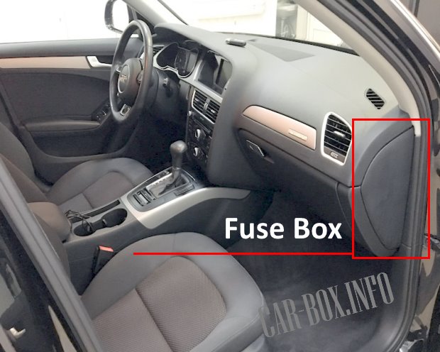
An additional fuse panel is located at the outer end of the dashboard on the passenger side.
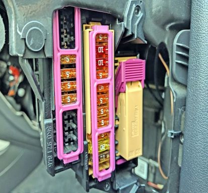
Accessing the passenger-side fuse panel.
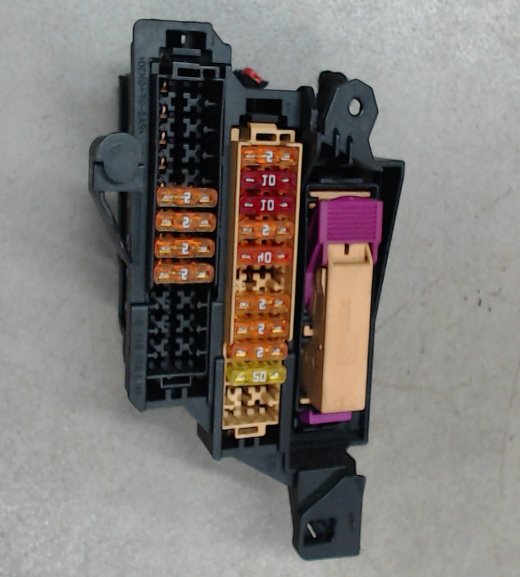
General overview.
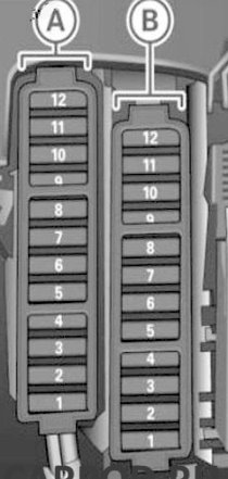
| Fuse Assignment (Model Years 2007–2011) | ||
|---|---|---|
|
||
| 2007–2009 Models | ||
| No. | A | Protected Component / Function |
| Black panel | ||
| 1 | — | — |
| 2 | — | — |
| 3 | — | — |
| 4 | — | — |
| 5 | 5 | Steering column switch module |
| 6 | 5 | Electronic Stability Program (ESP) |
| 7 | 5 | Data Link Connector (DLC) / Diagnostic port |
| 8 | 5 | Data bus diagnostic interface (Gateway) |
| 9 | — | — |
| 10 | — | — |
| 11 | — | — |
| 12 | — | — |
| Brown panel | ||
| 1 | 5 | CD drive |
| 2 | 5 | Audi Drive Select switch module |
| 3 | 10/20 | MMI / Radio |
| 4 | 5 | Control switch |
| 5 | 5 | Instrument cluster control module |
| 6 | 5 | Ignition lock |
| 7 | — | — |
| 8 | 40 | Climate control blower motor |
| 9 | 5 | Electronic steering column lock |
| 10 | 10 | Climate control system |
| 11 | 10 | Data Link Connector (DLC) / Diagnostic port |
| 12 | 5 | Steering column switch module |
| 2010–2011 Models | ||
| No. | A | Protected Component / Function |
| Black panel | ||
| 1 | — | — |
| 2 | — | — |
| 3 | — | — |
| 4 | — | — |
| 5 | 5 | Steering column switch module |
| 6 | 5 | Electronic Stability Program (ESP) |
| 7 | 5 | Data Link Connector (Terminal 15) |
| 8 | 5 | Data bus diagnostic interface (Gateway) |
| 9 | — | — |
| 10 | — | — |
| 11 | — | — |
| 12 | — | — |
| Brown panel | ||
| 1 | 5 | CD drive |
| 2 | 5 | Audi Drive Select switch module |
| 3 | 5/20 | MMI / Radio |
| 4 | 5 | Instrument cluster |
| 5 | 5 | Data bus diagnostic interface (Gateway) |
| 6 | 5 | Ignition lock |
| 7 | 5 | Rotary light switch |
| 8 | 40 | Climate control blower motor |
| 9 | 5 | Electronic steering column lock |
| 10 | 10 | Climate control system |
| 11 | 10 | Data Link Connector (Terminal 30) |
| 12 | 5 | Steering column switch module |
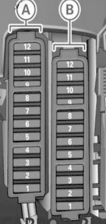
| Fuse Assignment (Model Years 2011–2015) | ||
|---|---|---|
|
||
| 2011–2013 Models | ||
| No. | A | Protected Component / Function |
| Black panel A | ||
| 1 | — | — |
| 2 | — | — |
| 3 | — | — |
| 4 | — | — |
| 5 | 5 | Steering column switch module |
| 6 | 5 | Electronic Stability Program (ESP) |
| 7 | 5 | Data Link Connector (Terminal 15) |
| 8 | 5 | Data bus diagnostic interface (Gateway) |
| 9 | — | — |
| 10 | — | — |
| 11 | — | — |
| 12 | — | — |
| Brown panel B | ||
| 1 | 5 | CD/DVD drive |
| 2 | 5 | Audi Drive Select switch module |
| 3 | 5/20 | MMI / Radio |
| 4 | 5 | Instrument cluster |
| 5 | 5 | Gateway (Instrument cluster control module) |
| 6 | 5 | Ignition lock |
| 7 | 5 | Rotary light switch |
| 8 | 40 | Climate control blower motor |
| 9 | 5 | Electronic steering column lock |
| 10 | 10 | Climate control system |
| 11 | 10 | Data Link Connector (Terminal 30) |
| 12 | 5 | Steering column switch module |
| 2014–2015 Models | ||
| No. | A | Protected Component / Function |
| Black panel A | ||
| 1 | — | — |
| 2 | — | — |
| 3 | — | — |
| 4 | — | — |
| 5 | 5 | Steering column switch module |
| 6 | — | — |
| 7 | 5 | Data Link Connector (Terminal 15) |
| 8 | 5 | Data bus diagnostic interface (Gateway) |
| 9 | 5 | Auxiliary heater |
| 10 | — | — |
| 11 | — | — |
| 12 | — | — |
| Brown panel B | ||
| 1 | 5 | CD/DVD drive |
| 2 | 5 | Wi-Fi module |
| 3 | 5/20 | MMI / Radio |
| 4 | 5 | Instrument cluster |
| 5 | 5 | Gateway (Instrument cluster control module) |
| 6 | 5 | Ignition lock |
| 7 | 5 | Control switch |
| 8 | 40 | Climate control blower motor |
| 9 | 5 | Electronic steering column lock |
| 10 | 10 | Climate control system |
| 11 | 10 | Data Link Connector (Terminal 30) |
| 12 | 5 | Steering column switch module |
Under the Dashboard
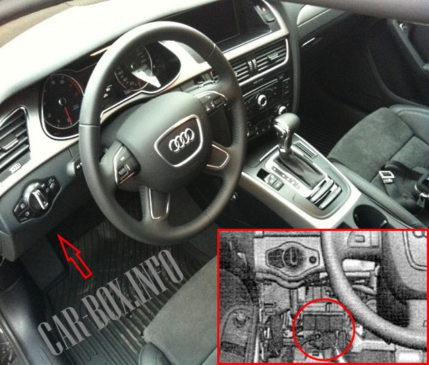
The onboard supply control module (Body Control Module / BCM) is located on the driver side under the dashboard.
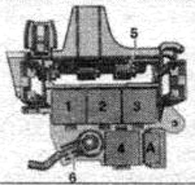
|
|
| No. | Description |
| A | ABS fuse -S123- |
| 1 | Unassigned |
| 2 | Coolant circulation pump relay, horn relay -J413-, vacuum pump -J318-, auto-dimming interior mirror -J910- |
| 3 | Terminal 15 power supply relay -J329- |
| 4 | Taxi anti-theft alarm system remote control module -J601- |
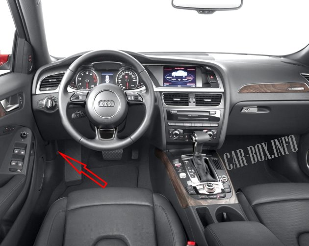
The 6-pin relay/fuse carrier is located on the A-pillar behind the side trim panel in the driver's footwell.
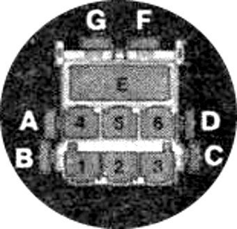
|
||
| No. | Description | A |
| F | Front passenger seat thermal fuse / circuit breaker | 15 |
| G | Driver seat thermal fuse / circuit breaker | 15 |
In the Engine Compartment

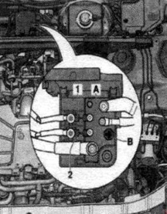
Electronics box (E-box) #1 is located on the left side of the engine compartment. Fuse carrier #2 is located in the center of the plenum chamber.
| E-box #1 Layout | ||
|---|---|---|

|
||
| No. | Description (Model Years 2007–2011) | A |
| 1 | Transmission Control Module (TCM) / Dual-clutch gearbox mechatronics unit | 15 |
| 2 | Engine oil level and temperature sensor | 5 |
| 3 | Engine Control Module (ECM) / Mass air flow (MAF) sensor | 5 |
| 4 | Engine Control Module (ECM) | 5 |
| 5 | Mass air flow sensor, glow plug control module, secondary air injection (AIR) pump relay, low-heat relay, high-heat relay, boost pressure control solenoid valve, crankcase ventilation heating element, EVAP canister purge solenoid valve 1, secondary air inlet valve, left electro-hydraulic engine mount solenoid valve, right electro-hydraulic engine mount solenoid valve, intake manifold changeover valve, air filter bypass valve, fuel pressure control valve, fuel metering valve, secondary air inlet valve 2, EGR cooler changeover valve, oil pressure control valve, fuel system diagnostic pump | 15/10/20 |
| 6 | Engine Control Module (ECM) | 15 |
| 7 |
|
15/10 |
| 8 | EGR cooler pump -V400-, ignition coils 1–6 with output stages | 5/20/10 |
| 9 | Auxiliary fuel pump relay, oxygen sensor 1 heater (downstream of catalytic converter), oxygen sensor 2 heater (downstream of catalytic converter) | 15/20/5 |
| 10 | Oxygen sensor heater, oxygen sensor 2 heater, oxygen sensor 1 heater (downstream of catalytic converter) | 15/10 |
| 11 | Radiator fan control module, radiator fan control module 2 | 5 |
| 12 | Mass air flow sensor, dual-clutch transmission mechatronics control module | 5 |
| A | Engine component power supply relay, automatic glow plug system relay | |
| B | Starter relay 2 | |
| C | Secondary air injection (AIR) pump relay | |
| D | Motronic system power supply relay, Terminal 30 power supply relay | |
| E | Fuel pump relay, transmission cooling circuit, engine component power supply 2, run-on coolant pump | |
| F | Unassigned | |
| No. | Description (Model Years 2011–2015) | A |
| 1 | Transmission Control Module (TCM) — Dual-clutch gearbox mechatronics unit | 15 |
| 2 | Engine oil level and temperature sensor | 5 |
| 3 | Engine Control Module (ECM) | 5 |
| 4 | 5 | |
| 5 | Mass air flow sensor, fuel pressure control valve, fuel metering valve | 10/15 |
| 6 | Engine Control Module (ECM) — Cylinder 1–4 injectors (Group 2) | 15 |
| 7 | Camshaft timing actuators 1–8, boost pressure control solenoid valve, EVAP canister purge solenoid valve 1, left electro-hydraulic engine mount solenoid valve, right electro-hydraulic engine mount solenoid valve, variable valve timing valves 1 & 2, charge air recirculating valve, fuel pressure control valve | |
| 8 | NOx sensor 2, NOx sensor 2 control module | 10/15/5 |
| 9 | Voltage regulator, Engine Control Module (ECM) | 5 |
| 10 | Oxygen sensor heater | 15/10 |
| 11 | Radiator fan control module | 5 |
| 12 | Transmission Control Module (TCM) | 5 |
| 13 | Unassigned | - |
| 14 | Engine component power supply relay 2, ignition coil 1 with output stage | 5/20 |
| 15 | Power steering control module | 5 |
| 16 | Map-controlled engine cooling thermostat, automatic glow plug control module | 15 |
| 17 | Downstream oxygen sensor heater | 15 |
| A | Engine component power supply relay | |
| B | Starter relay 2 | |
| C | Secondary air injection (AIR) pump relay | |
| D | Motronic system power supply relay | |
| E | Fuel pump relay, transmission cooling circuit, engine component power supply 2, run-on coolant pump | |
| F | Unassigned | |
| Fuse Carrier #2 | ||
|---|---|---|
|
||
| No. | Description | A |
| 1 | 400 W / 600 W radiator fan control module | 40/60 |
| 2 | 400 W radiator fan control module | 40 |
