
The A4 (B7) is the third generation of Audi's mid-size vehicle, produced from 2004 to 2007. It is a heavily revised version of the B6 platform. In this article, we will provide a detailed overview of the fuse box diagrams for the third-generation Audi A4 (B7) 2004, 2005, 2006, 2007, 2008, and 2009 equipped with gasoline and diesel engines, including the 1.6 8V, 1.8 20V Turbo, 1.9 TDI, 2.0 FSI, 2.4 V6, 2.5 TDI V6, 3.0 V6, and 4.2 V8.
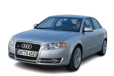
Below, you will find the locations and diagrams of the power distribution boxes. The fuses responsible for the "Cigarette Lighter" and "Fuel Pump" are highlighted in bold.
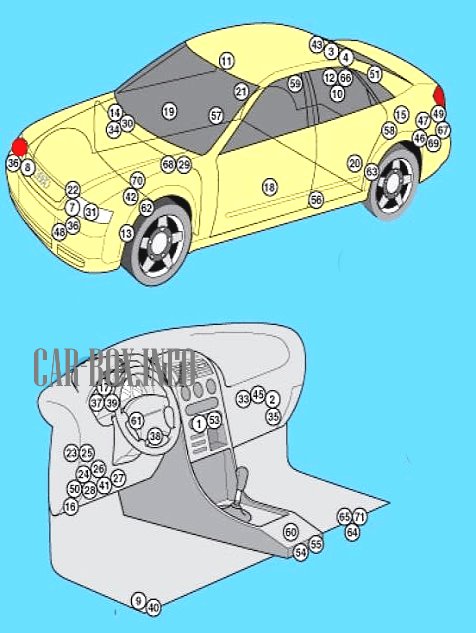
General Layout
Location of electronic control modules and components.
|
|
| No. | Component |
| 1 | HVAC control module - in the climate control panel - functions: Rear window defroster, front seat heating, steering wheel heating |
| 2 | Blower motor control module - blower motor assembly |
| 3 | Antenna selection control module (Sedan with "Concert II / Symphony II" audio system) - rear headliner, center |
| 4 | Antenna amplifier (Sedan with "Chorus II" audio system) - rear headliner, center |
| 7 | Crash sensor, driver side - engine compartment |
| 8 | Crash sensor, passenger side - engine compartment |
| 9 | Vehicle inclination sensor (anti-theft alarm system) - integrated into multifunction control module 2 |
| 10 | Anti-theft alarm siren - luggage compartment, behind right side trim panel |
| 11 | Interior motion sensor (anti-theft alarm system) - front dome light assembly |
| 12 | Audio amplifier - luggage compartment, behind right side trim panel |
| 13 | Auxiliary heater control module - behind left front wheel arch |
| 14 | Battery |
| 15 | Radio clock receiver module (with digital multifunction display) - behind rear bumper |
| 16 | Data Link Connector (DLC) - under dashboard, driver side |
| 17 | Gateway control module - inside dashboard |
| 18 | Door control module, front left (central locking / power mirror / power window) - inside door |
| 19 | Door control module, front right (central locking / power mirror / power window) - inside door |
| 20 | Door control module, rear left (central locking / power window) - inside door |
| 21 | Door control module, rear right (central locking / power window) - inside door |
| 22 | Radiator cooling fan control module - mounted on radiator |
| 23 | Fuse/Relay boxes behind dashboard |
| 24 | |
| 25 | |
| 26 | |
| 27 | Fuse/Relay box 5, dashboard - Taxi models |
| 28 | Fuse/Relay box 6, dashboard - Taxi models |
| 29 | Fuse/Relay box, engine compartment - under ECM/TCM (plenum chamber) |
| 30 | Main fuse (150 A) - at battery |
| 31 | Headlight range control module, left (xenon headlight models) |
Engine Compartment
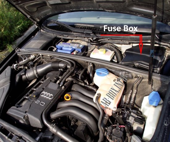
The power distribution box is located in the engine compartment beneath the Engine Control Module (ECM) and Transmission Control Module (TCM).
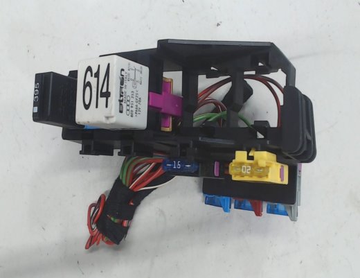
General view (cover removed for clarity).
| Diagram | ||
|---|---|---|
| Diesel Engines | ||

|
||
| No. | Description | A (Amperage) |
| F1 | Engine control system, brake light switch (brake pedal position sensor) | 15 |
| F2 | Glow plugs | 60/80 |
| F3 | Transmission control module (6-speed automatic / Multitronic) | 15 |
| F4 | Glow plugs | 60 |
| 1 | Fuel pump relay | |
| 2 | Transmission control relay (Multitronic) | |
| 3 | Glow plug relay | |
| 4 | Engine control relay | |
| 5 | Starter interlock relay / reverse light relay (Multitronic) | |
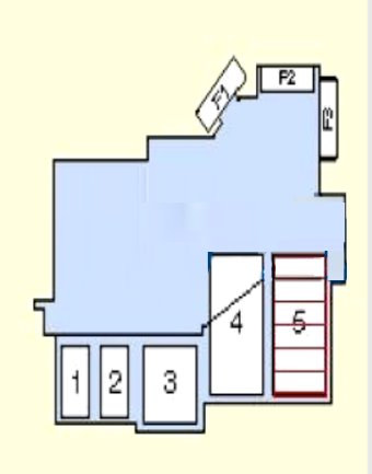
| Gasoline Engines | ||
|
||
| No. | Description | A (Amperage) |
| F1 | Engine control system, brake light switch (brake pedal position sensor) | 15 |
| F2 | Secondary air injection (SAI) pump motor (if equipped) | 40 |
| F3 | Transmission control module (6-speed automatic / Multitronic) | 15 |
| 1 | Coolant heater relay (V6) (if equipped) | |
| 2 | Transmission control relay (Multitronic) | |
| 3 | Secondary air injection (SAI) pump relay | |
| 4 | Afterrun coolant pump control module (AMM/BDV) (if equipped) | |
| 5 | Starter interlock relay (if equipped) | |
Passenger Compartment
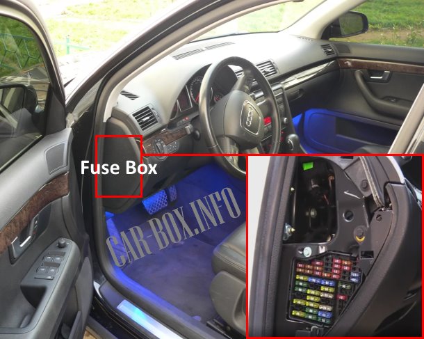
There are four fuse and relay blocks within the passenger compartment. The main interior fuse box is located behind the side cover of the dashboard on the driver's side.
Main Fuse Box
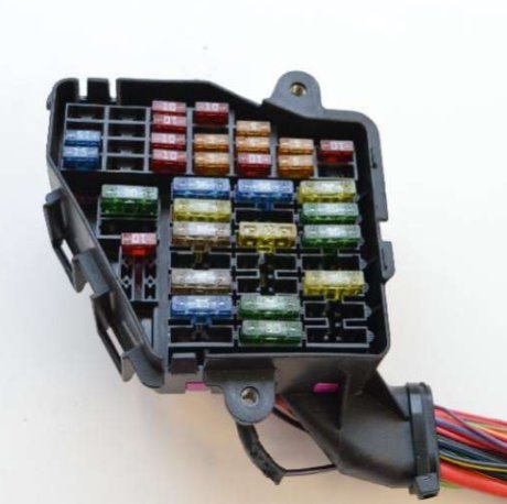
General layout
| Diagram | ||
|---|---|---|
|
||
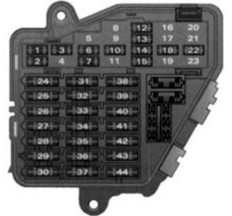
| No. | A (Amperage) | Description |
| 1 | 10 | Climate control system |
| 2 | 5 | Footwell lighting |
| 3 | 5 | Heated windshield washer nozzles |
| 4 | 5 | Radiator cooling fan |
| 5 | 10 | Telephone, engine oil level sensor, multifunction switches, heated rear seats, rear sunblind, automatic transmission (selector lever mechanism) |
| 6 | 5 | Climate control (air quality sensor), A/C pressure sensor |
| 7 | 10 | Electronic Stability Program (ESP), brake light switch, clutch pedal switch, steering angle sensor |
| 8 | 5 | Telephone |
| 9 | 15 | Brake booster (vacuum pump) |
| 10 | 5 | Automatic headlight range control. Adaptive lighting (cornering light), right |
| 11 | - | Empty |
| 12 | 10 | Data Link Connector (DLC) |
| 13 | 10 | Steering column control module |
| 14 | 10 | Brake lights |
| 15 | 10 | Instrument cluster, navigation system |
| 16 | 5 | Garage door opener (HomeLink) |
| 17 | 10 | Parking aid, adaptive air suspension, tire pressure monitoring system (TPMS), rain/light sensor |
| 18 | 5 | Adaptive lighting (cornering light), left |
| 19 | 15 | Fog lights |
| 20 | Empty | |
| 21 | Not used | |
| 22 | 15 | Driver / front passenger door control modules |
| 23 | 15 | Rear door control modules |
| 24 | 20 | Central convenience control module |
| 25 | 30 | HVAC blower motor |
| 26 | 30 | Rear window defroster |
| 27 | 30 | Trailer towing module |
| 28 | 20 | Fuel pump control module, auxiliary diesel fuel pump |
| 29 | - | Not used |
| 30 | 20 | Power sunroof |
| 31 | 15 | Automatic transmission, Data Link Connector (DLC), auto-dimming interior rearview mirror |
| 32 | 20 | Trailer socket |
| 33 | 15 | Cigarette lighter |
| 34 | - | Not used |
| 35 | 20 | 12V power outlet in luggage compartment |
| 36 | 30 | Windshield wipers |
| 37 | 30 | Windshield washer pump and headlight washer system |
| 38 | 15 | Central convenience control module, trunk release |
| 39 | 20 | Radio / infotainment system |
| 40 | 25 | Horn |
| 41 | 30 | Auxiliary heater |
| 42 | 25 | Electronic Stability Program (ESP) |
| 43 | 15 | Engine control module (ECM) |
| 44 | 35 | Heated seats |
Additional Relay Blocks
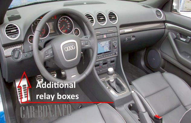
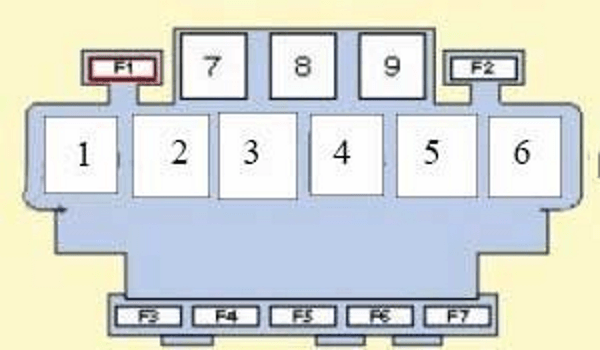
Located behind the driver's side lower dash trim. To access these relays, you must remove the knee bolster panel beneath the steering column.
| Relay Box #1 | ||
|---|---|---|
|
||
| No. | Description | A (Amperage) |
| F1 | Empty | - |
| F2 | Thermal circuit breaker for power rear sunblind | 10 |
| F3 | Empty | - |
| F4 | Thermal circuit breaker for rear power windows | 30 |
| F5 | Power seats (lumbar support adjustment) | 10 |
| F6 | Thermal circuit breaker for front power windows | 30 |
| F7 | Trailer wiring harness | 30 |
| 1 | Fuel pump relay - gasoline engines | |
| 2 | Power steering (Servotronic) control module (if equipped) | |
| 3 | Dual-tone horn relay | |
| 4 | Brake booster vacuum pump relay (if equipped) | |
| 5 | Empty | |
| 6 | Ignition / accessory power relay | |
| 7 | Empty | |
| 8 | Empty | |
| 9 | Empty | |
| Relay Box #2 | ||
|---|---|---|

|
||
| No. | Description | A (Amperage) |
| A | Empty | - |
| B | Optional equipment | |
| C | Empty | - |
| D | Empty | - |
| E | Anti-lock Braking System (ABS) relay | 50 |
| F | Radiator cooling fan control module 1 relay | 40/60 |
| G | Special vehicles / police / taxi preparation | 10 |
| H | Radiator cooling fan control module 2 relay (if equipped) | |
| 1 | Empty | |
| 2 | Empty | |
| 3 | Empty | |
| 4 | Alarm system / hands-free control module (Taxi models) | |
| Relay Box #3 | ||
|---|---|---|
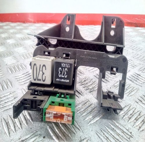
General layout. |
||
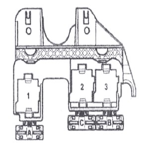
Diagram. |
||
| No. | Description | A (Amperage) |
| A | Auxiliary heater relay | 30 |
| C | PTC auxiliary coolant heater | 40 |
| B | 60 | |
| 1 | Empty | |
| 2 | Auxiliary coolant heater relay 2 - high output | |
| 3 | Auxiliary coolant heater relay 1 - low output | |

Where would I look for a, 2006 A4 Quattro 2.0t? It gives you no option. 2005 then skips 2 years to 2007? What's the deal? Is there some secret about the 2006 Audi A4..? Real though these parts are getting pretty expensive. Really could use a lay out, diagram something of that years relay\ fuse box.
All B7 A4 (late 2005 to early 2008) are the same vehicle (same diaphragm)
Thank you for posting this information. I’ve seen other posts on the net regarding relay and fuse diagrams, but this one is much more thorough and descriptive.
Currently diagnosing a no A/C/blower fan motor condition. What’s really weird is I have tested every single relay and every single fuse and they all test as functional. At this point, I am checking the actual wire that goes to the blower motor and checking for Continuity. It’s weird because there’s no black burn marks on the wire at the connector or on the wire even tracing serval feet of it there’s nothing showing that it has been damaged.