The Audi A5 is a sports car (two-door coupe on the A4 platform) produced by the German automaker since 2007 at the Ingolstadt plant. In this article, we will take a detailed look at the fuse diagrams for the the Audi A5 (8T) 1st generation 2007, 2008, 2009, 2010, 2011, 2012, 2013, 2014, 2015, 2016 release.
Here you will find the locations and photos of distribution boxes. The fuses responsible for the “Cigarette lighter” and “Fuel Pump” are highlighted in bold.
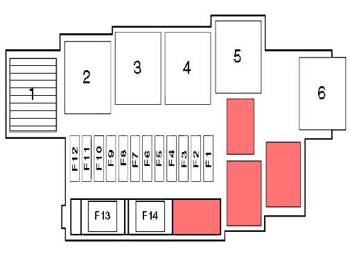
In the engine compartment
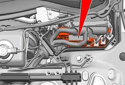
The distribution box is located on the right side and is closed with a plastic cover.
| Assigment of fuses and relays in the engine compartment | ||
|---|---|---|
|
||
| No. | Description | A |
| F1 | Electronic gearbox control unit | 15 |
| F2 | Engine Oil Condition Sensor | 5/10 |
| F3 | Reserve | 5 |
| F4 | Electronic engine control unit | 5 |
| F5 | Engine control/system | 10/15/20 |
| F6 | Electronic engine control unit | 15 |
| F7 | Engine management system | 10/50 |
| F8 | System/engine management | 5/10/15/20/30 |
| F9 | Engine management system | 5/15/25 |
| F10 | Engine management system | 10/15 |
| F11 | Reserve | 5 |
| F12 | Reserve | 5 |
| F13 | Reserve | 15/50 |
| F14 | Diesel: Glow plugs | 60/80 |
| 1 | Diesel: Glow Plug Timer Relay | |
| 2 | Starter relay | |
| 3 | Empty | |
| 4 | Diesel: Engine management relay | |
| 5 | Empty | |
| 6 | Empty | |
In the passenger compartment
From the driver's side

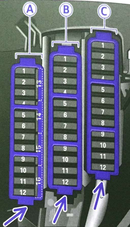
The first block is located on the driver's side at the end of the instrument panel behind a plastic cover.
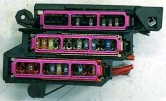
Photo - an example of the driver's unit (removed for clarity).
| Diagram | ||
|---|---|---|
|
||
| No. | A | Description |
| panel A | ||
| 1 | 5 | Dynamic Steering |
| 2 | 5 | Electronic stabilization control (module) |
| 3 | 5 | Air conditioning pressure sensor, electromechanical parking brake, Homelink, auto-dimming interior rearview mirror, air quality/outside air sensor, electronic stability control (button) |
| 4 | — | — |
| 5 | 5 | sound drive |
| 6 | 5 / 7.5 | Headlight range adjustment / head light (corner light) |
| 7 | 7.5 | Headlight (turning light) |
| 8 | 5 | Control modules (electromechanical parking brake, shock absorber, quattro sport), DCDC converter |
| 9 | 5 | Adaptive cruise control |
| 10 | 5 | Shift/Clutch Door Sensor |
| 11 | 5 | Lateral assistance |
| 12 | 5 | Headlight range adjustment, parking system |
| 13 | 5 | Air bag |
| 14 | 15 | Rear wiper (allroad) |
| 15 | 10 | Auxiliary fuse (dashboard) |
| 16 | 40 | Auxiliary fuse terminal 15 (engine area) |
| Panel B | ||
| 1 | — | — |
| 2 | 5 | Stop light sensor |
| 3 | 25 | Fuel module (fuel pump fuse) |
| 4 | 5 | clutch sensor |
| 5 | 15/30 | Left seat heating with / without seat ventilation |
| 6 | 5 | Electronic stabilization control (electric) |
| 7 | 15 | Horn |
| 8 | 30 | Front left door (power window, central locking, mirror, switch, lighting) |
| 9 | 30 | Windshield wiper motor |
| 10 | 25 | Electronic stabilization control (valves) |
| 11 | 30 | Two-door models: rear left power window, Four-door models: rear left door (power window, central locking, switch, lighting) |
| 12 | 5 | Rain and light sensor |
| panel C | ||
| 1 | — | — |
| 2 | — | — |
| 3 | 10 | Lumbar support |
| 4 | 35 | Dynamic Steering |
| 5 | 5 | Interior lighting (Convertible) |
| 6 | 35 | Windshield washer, headlight washer |
| 7 | 20 | Onboard supply control module 1 |
| 8 | 30 | Onboard supply control module 1 |
| 9 | 7.5 / 20 | Power window motor, left (convertible) / sunroof |
| 10 | 30 | Onboard supply control module 1 |
| 11 | 7.5 / 20 | Right rear power window (Cabriolet sunshade motor) |
| 12 | 5 | Theft warning system |
From the passenger's side
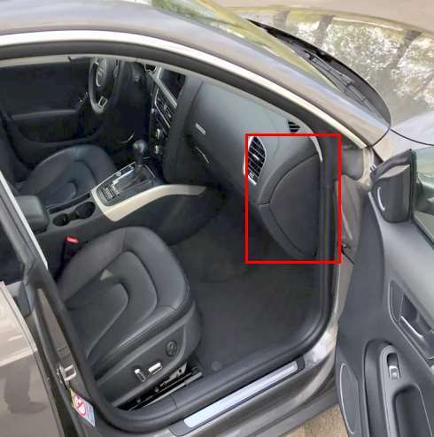
The second fuse box is located at the end of the dashboard on the passenger side.
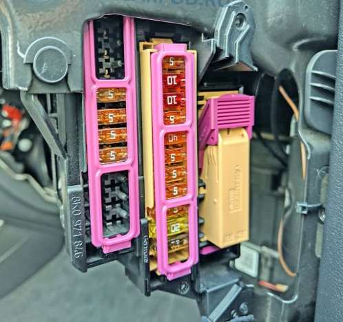
Access example.
| Diagram | ||
|---|---|---|
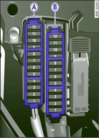
Diagram. |
||
| No. | A | Purpose |
| panel A | ||
| 1 | — | — |
| 2 | — | — |
| 3 | — | — |
| 4 | — | — |
| 5 | 5 | Steering column switch module |
| 6 | — | — |
| 7 | 5 | Terminal 15 of the diagnostic socket |
| 8 | 5 | Gateway (data bus diagnostic interface) |
| 9 | 5 | Additional heater |
| 10 | — | — |
| 11 | — | — |
| 12 | — | — |
| panel B | ||
| 1 | 5 | CD/DVD player |
| 2 | 5 | Wi-Fi |
| 3 | 5/20 | MMI / Radio |
| 4 | 5 | instrument panel |
| 5 | 5 | Gateway (instrument cluster control module) |
| 6 | 5 | Egnition lock |
| 7 | 5 | Switch |
| 8 | 40 | climate control blower |
| 9 | 5 | Steering column lock |
| 10 | 10 | Climate control system |
| 11 | 10 | Terminal 30 of the diagnostic socket |
| 12 | 5 | Steering column switch module |
In the trunk
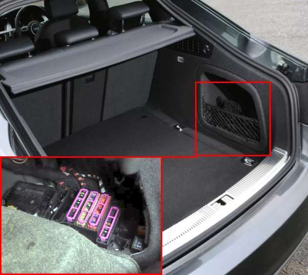
It is located behind the casing on the right side.

The photo shows an example.
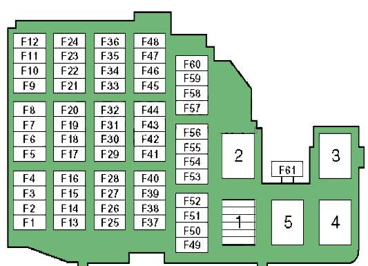
| Assigment of fuses in the luggage compartment | ||
|---|---|---|
|
||
| No. | Purpose | A |
| F1 | empty | — |
| F2 | empty | — |
| F3 | empty | — |
| F4 | empty | — |
| F5 | empty | — |
| F6 | empty | — |
| F7 | empty | — |
| F8 | empty | — |
| F9 | empty | — |
| F10 | empty | — |
| F11 | empty | — |
| F12 | empty | — |
| F13 | ^2009: Tire pressure monitoring control unit | 5 |
| F14 | Spare | 10 |
| F15 | Trailer control unit | 20 |
| F16 | 20 | |
| F17 | Parking brake | 5 |
| F18 | Suspension control unit | 15 |
| F19 | Parking brake control unit | 30 |
| F20 | Spare | 30 |
| F21 | Electronic control unit 4WD | 35 |
| F22 | Spare | 30 |
| F23 | Spare | 20 |
| F24 | Spare | 5 |
| F25 | ( ^2009: Voltage converter | 15/30 |
| F26 | empty | - |
| F27 | Audio system | 7.5/40 |
| F28 | Spare | 30/40 |
| F29 | Spare | 5/30 |
| F30 | Additional heater control unit | 30 |
| F31 | Parking brake control unit | 30 |
| F32 | Rear seat heater | 30 |
| F33 | Door function control units | 30 |
| F34 | Auxiliary heater remote control receiver | 5 |
| F35 | Door function control units | 15 |
| F36 | ^2009: Rear view camera control unit | 5 |
| F37 | Accessory Power Connectors | 15 |
| F38 | 15 | |
| F39 | 15 | |
| F40 | Cigarette lighter fuse Audi A5 | 15 |
| F41 | ^2009: Parktronic control unit | 5 |
| F42 | Spare | 5 |
| F43 | Spare | 5/7.5 |
| F44 | empty | |
| F45 | Parking brake | 5 |
| F46 | Spare | 5 |
| F47 | Rear seat heater | 5 |
| F48 | Spare | 5 |
| F49 | empty | - |
| F50 | empty | - |
| F51 | ^2009: Not used | - |
| F52 | ^2009: Not used | - |
| F53 | ^2009: Not used | - |
| F54 | ^2009: Not used | - |
| F55 | ^2009: Not used | - |
| F56 | empty | - |
| F57 | empty | - |
| F58 | empty | - |
| F59 | empty | - |
| F60 | empty | - |
| F61 | Rear window heater | 40 |
| 1 | empty | - |
| 2 | Audio system relay | - |
| 3 | Rear defroster relay | - |
| 4 | Main Ignition Relay | - |
| 5 | Accessory Power Connector Relay | - |
