The first generation of the Audi A4 was produced until 2001 with minor changes. At first, only the sedan version was available, the wagon version (Avant) appeared a year later. The car was based on the same platform as the fifth generation Volkswagen Passat. In dimensions, the A4 practically does not differ from the Audi 80. In this material, we will analyze in detail all the fuse diagrams of the first Audi A4 (1994, 1995, 1996, 1997, 1998, 1999, 2000, 2001 year of manufacture, body B5).
Here you will find the locations and photos of distribution boxes. Separately, we note the fuses responsible for the fuel pump and cigarette lighter.
In the passenger compartment
Fuse box
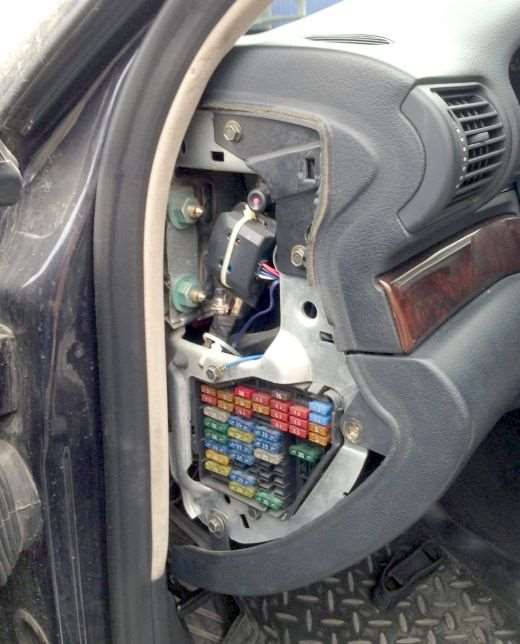
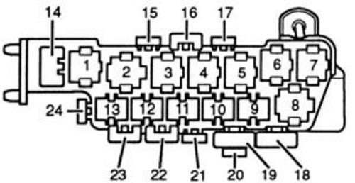
The main distribution box is located at the end of the dashboard on the driver's side.
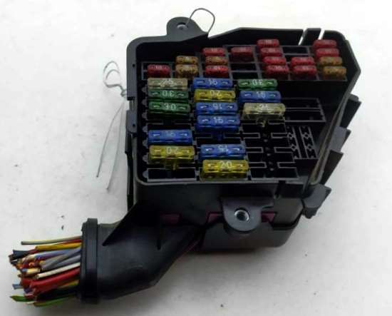
General view.
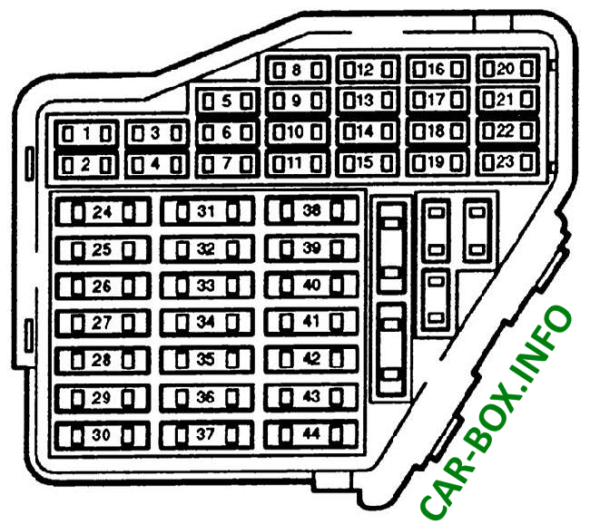
| Fuse Diagram | ||
|---|---|---|
|
||
| No. | A | Decryption |
| 1 | 5 | Heated washer nozzles |
| 2 | 10 | direction indicators |
| 3 | 5 | Headlight washer relay. Lighting; glove box. engine compartment, air conditioning, automatic transmission. dashboard |
| 4 | 5 | License plate lighting |
| 5 | 10 | Dashboard, heated seats, automatic transmission display. mirror switch, airbag lamp, outside temperature gauge, navigation system, parking lights |
| 6 | 5 | central locking |
| 7 | 10 | ABC system |
| 8 | 5 | Telephone |
| 9 | 10 | Mirror and door lock heater |
| 10 | 5 | Headlights corrector |
| 11 | 5 | Cruise control (automatic transmission) |
| 12 | 10 | Built-in diagnostics |
| 13 | 10 | Stop lights |
| 14 | 10 | Interior lighting, reading lights, anti-theft system, passenger visor mirror |
| 15 | 10 | Dashboard, automatic transmission [4-speed], air conditioning, navigation system |
| 16 | 5 | ABC system |
| 17 | 10 | Heated door locks |
| 18 | 10 | right high beam |
| 19 | 10 | left high beam |
| 20 | 15 | Right dipped beam, electric headlight corrector |
| 21 | 15 | Left dipped beam, headlight range control |
| 22 | 5 | Right marker lights |
| 23 | 5 | Left marker lights |
| 24 | 25 | Windshield Wipers, Washer Pump, Wiper Breaker Relay |
| 25 | 30 | Heating fan, air conditioner |
| 26 | 30 | Heated rear window, heated mirrors, air recirculation |
| 27 | - | - |
| 28 | 15 | Engine management |
| 30 | 20 | Power sunroof |
| 31 | 15 | Reversing lights, cruise control, automatic transmission, diagnostic socket |
| 32 | 20 | Engine management |
| 33 | 15 | cigarette lighter fuse |
| 34 | 15 | Engine management |
| 35 | 30 | Trailer socket |
| 36 | 15 | Phone, radio |
| 38 | 15 | Trunk lighting, central locking |
| 39 | 15 | Emergency lighting |
| 40 | Klaxon | |
| 41 | 25 | ABS system [hydraulic modulator/pump) |
| 42 | 40 | Fan |
| 43 | 5 | S-contact [central locking, radio, navigation system |
| 44 | 30 | Heated seats |
Auxilary fuse box
Diagram.
|
||
| № | Description | A |
| 18 | ABS hydraulic pump | 50 |
| 19 | Electric radiator fan | 40 |
| 21 | Radiator fan relay coil | 5 |
| 22 | Rear power window lifter | 30 |
| 23 | Power window, front | 30 |
| 24 | Central locking and anti-theft alarm system | 15 |
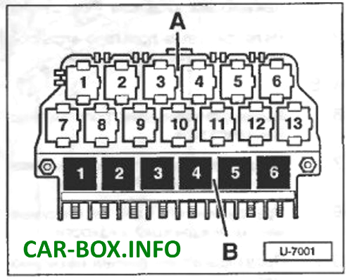
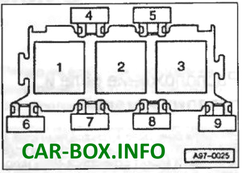
Relay box
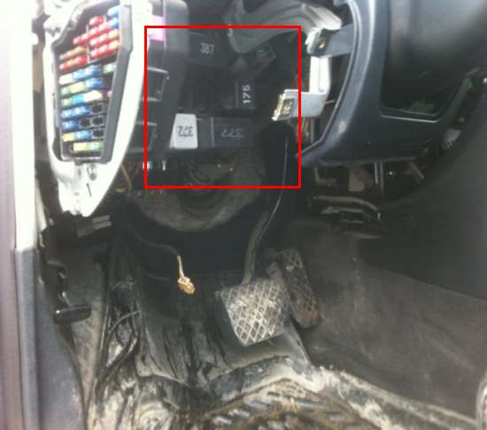
The relay modules are located on the central distribution block under the dashboard.
| Diagram | |
|---|---|
|
|
| № | Description |
| 1 | Unloading relay for contact X |
| 2 | Horn relay |
| 3 | Headlight lens cleaning relay |
| 4 | Automatic transmission relay (starter interlock and reversing lights] or, respectively, a jumper for a manual transmission |
| 5 | Intermittent mode relay for cleaning and flushing system |
| 6 | Relay for fuel pump or glow plugs |
| Relay main board - A | |
| 3 | Electromagnetic clutch relay (air conditioning) |
| 4 | Signaling device control unit |
| 5 | |
| 7 | - |
| 8 | Daytime running light relay |
| 9 | Headlamp relay |
| 10 | Fog lamp relay |
| 11 | Control unit for folding mirror |
| 12 | |
| 13 | - |
| 14 | Fuse for special signaling system [taxi] |
| 15 | - |
| 16 | Fuse for special signaling system [taxi] |
| 17 | Fuse for taximeter [taxi] |
| 18 | System hydraulic pump fuse [ABS] Transmitter Fuse [Taxi] |
In the engine compartment
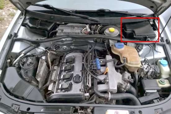
Under the hood there is an additional block with relay modules.
| Diagram | |
|---|---|
|
|
| № | Description |
| 1 | Heated oxygen sensor relay Glow plug relay I - coolant |
| 2 | Glow plug relay II - coolant |
| 3 | Diesel Direct Injection Relay |
| 4-5 | - |
| 6 | Fuse for engine electrical equipment |
| 7 | Glow plug fuse I - coolant |
| 8 | Fuse II for glow plugs - coolant |
| 9 | Glow plug fuse |
| Additional relay board | |
| 1 | Turnip rear fog lights |
| 2 | Fan operating mode relay at maximum speed [Lufter voll auf] |
| 3 | Relay for fan operation in the first stage |
| 4 | Power window control unit relay |
| 5-15 | - |
| 16 | Seat adjustment fuse |
| 17 | - |
| 18 | System hydraulic pump fuse (ABS) |
| 19 | Radiator fan fuse |
| 20 | - |
| 21 | Radiator fan changeover coil relay |
| 22 | Rear power window relay |
| 23 | Front power window relay |
| 24 | Relay for central locking and anti-theft system |
