
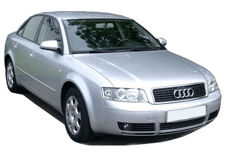
The Audi 80, renamed the A4 in 1995, is a family of mid-size vehicles produced by the German manufacturer. The internal chassis designation for this series is “Type B”. In this article, we examine the fuse and relay diagrams for the second-generation Audi A4 (B6), covering model years 2001, 2002, 2003, 2004, and 2005 equipped with gasoline and diesel engines.
Below are the component locations and photographs of the electrical power distribution centers. The fuses protecting the “Cigarette Lighter” and “Fuel Pump” circuits are highlighted in bold.
In the Engine Compartment
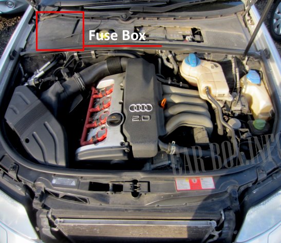
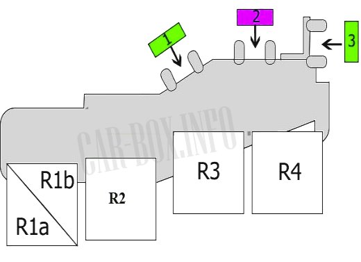
Located on the right side of the engine compartment, beneath the protective cowl cover.

Example photograph (cover removed for clarity).
| Engine Compartment Fuse & Relay Box Diagram | ||
|---|---|---|
|
||
| No. | Circuit / Component | A |
| 1 | Engine electronics, brake pedal switch | 15 |
| 2 | Secondary air injection (SAI) pump | 40 |
| 3 | Automatic transmission control module (TCM) | 15 |
| R1a | Automatic transmission relay | - |
| R1b | Not used | - |
| R2 | Secondary air injection (SAI) pump relay | - |
| R3 | Motronic Engine Control Module (ECM) power supply relay / Main relay | - |
| R4 | Starter interlock relay and reverse light relay, or automatic transmission relay | - |
In the Passenger Compartment
Main Fuse Panel
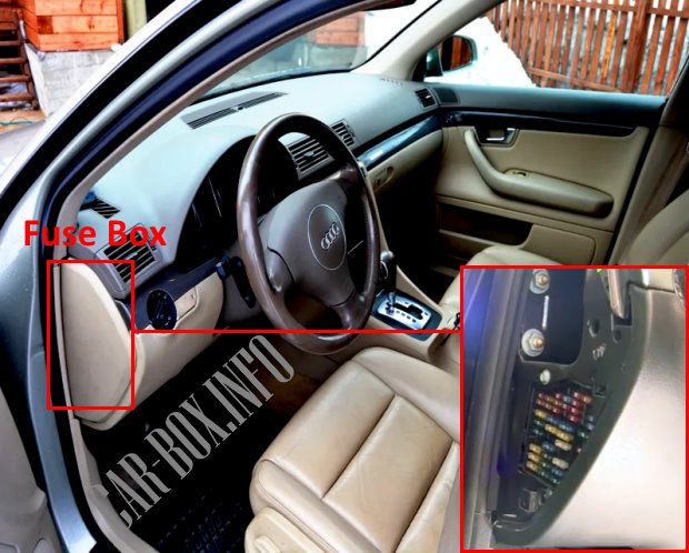
The main power distribution panel is located on the driver's side end of the dashboard behind the trim panel. To access the fuses, carefully pry off the side cover using a flathead screwdriver or trim tool.
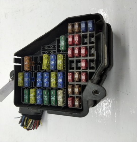
General view.
| Audi A4 (B6) Passenger Compartment Fuse Assignment | ||
|---|---|---|
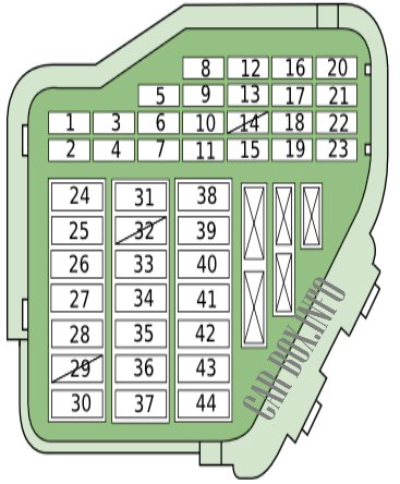
|
||
| No. | Circuit / Component | A |
| 1 | Air conditioning (A/C) system | 10 |
| 2 | Footwell lights, glove compartment light | 5 |
| 3 | Heated windshield washer nozzles | 5 |
| 4 | Radiator cooling fan control module | 5 |
| 5 | Automatic transmission control module, engine oil level/temperature sensor, heated rear seats, navigation system, power rear sunshade, telephone/telematics | 10 |
| 6 | Air conditioning (A/C) system | 5 |
| 7 | Anti-lock Braking System (ABS), brake pedal switch, clutch pedal switch | 10 |
| 8 | Telephone/telematics | 5 |
| 9 | Brake booster vacuum pump (if equipped) | 10 |
| 10 | Headlight leveling system | 10 |
| 11 | Automatic transmission (through 2001) | 10 |
| 12 | On-Board Diagnostics (OBD) port | 10 |
| 13 | Steering column control module | 10 |
| 14 | Brake lights | 10 |
| 15 | Instrument cluster, navigation system | 10 |
| 16 | HomeLink® garage door opener | 5 |
| 17 | Parking aid control module | 10 |
| 18 | Not used | - |
| 19 | Front and rear fog lights | 15 |
| 20 | Right headlight (low beam, headlight leveling) | 15 |
| 21 | Left headlight (low beam, headlight leveling) | 15 |
| 22 | Door control module (front left), door control module (rear left) (through 2001) | 15 |
| 23 | Door control module (front right), door control module (rear right) (through 2001) | 15 |
| 24 | Central convenience control module 2 (optional equipment) | 20/30 |
| 25 | HVAC blower motor | 30 |
| 26 | Rear window defogger | 30 |
| 27 | Trailer control module | 30 |
| 28 |
|
20 |
| 29 | Engine Control Module (ECM) - Gasoline | 20 |
| 30 | Power sunroof | 20 |
| 31 | Auto-dimming interior rearview mirror, automatic transmission control module, OBD port, Engine Control Module (ECM), reverse lights | 15 |
| 32 | Engine Control Module (ECM) - Gasoline | 20 |
| 33 | Audi A4 cigarette lighter fuse | 15 |
| 34 | Engine Control Module (ECM) - Gasoline | 15 |
| 35 | Auxiliary power outlet | 30 |
| 36 | Central convenience control module 1, windshield wipers/washers | 30 |
| 37 | Central convenience control module 1, headlight washers | 20/25 |
| 38 | Anti-theft alarm system, tailgate release, central convenience control module 2 | 15/30 |
| 39 | Audio system, navigation system | 20/30 |
| 40 | Dual-tone horn | 25 |
| 41 | Auxiliary heater (2003 onwards) | 30 |
| 42 | Anti-lock Braking System (ABS), Electronic Stability Program (ESP) | 25 |
| 43 | Engine Control Module (ECM) - Gasoline | 15 |
| 44 | Heated seats, heated steering wheel | 30 |
Auxiliary Relay Panels
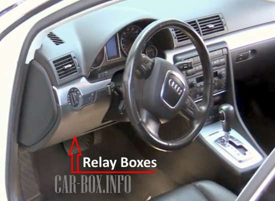
Located behind the driver's side lower dashboard trim (knee bolster).
| Auxiliary Relay Panel Assignments (Audi A4 B6) | ||
|---|---|---|
| Panel #1 | ||
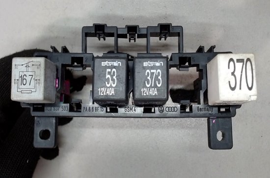
General view. |
||

Diagram. |
||
| No. | Circuit / Component | A |
| F1 | Power rear sunshade | 10 |
| F2 | 10 | |
| F3 | Not used | 3 |
| F4 | Rear power windows | 30 |
| F5 | Power seats | 10 |
| F6 | Front power windows | 30 |
| F7 | Trailer control module | 30 |
| 1 | Fuel pump relay | - |
| 2 | Servotronic power steering relay | - |
| 3 | Horn relay | - |
| 4 | Brake booster vacuum pump relay | - |
| 5 | Not used | - |
| 6 | Load reduction relay (Circuit 75x) | - |
| 7 | Not used | - |
| 8 | - | |
| 9 | - | |
| Panel #2 | ||
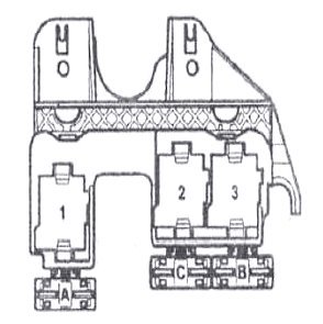
|
||
| No. | Protected Circuit | A |
| A | Auxiliary heater | 30 |
| C | Auxiliary coolant heater | 40 |
| B | 60 | |
| 1 | Not used | |
| 2 | Auxiliary coolant heater relay 2 (High output) | |
| 3 | Auxiliary coolant heater relay 1 (Low output) | |
| Panel #3 | ||
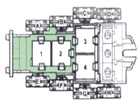
|
||
| No. | Circuit / Component | A |
| A | Not used | - |
| B | - | |
| C | - | |
| D | - | |
| E | Radiator cooling fan relay | 40 |
| F | Auxiliary equipment fuse | 10 |
| G | Radiator cooling fan fuse (also 60A optional) | 40 |
| H | ABS control module fuse | 50 |
| 1 | Not used | - |
| 2 | - | |
| 3 | - | |
| 4 | Taxi alarm control module 3 relay | - |
