The A8 is a luxury car manufactured by Audi AG in Neckarsulm, Germany, the successor to the V8. In this article, we will take a detailed look at the fuse box diagrams for the Audi A8 (D3 / 4E) of the 2nd generation of 2002, 2003, 2004, 2005, 2006, 2007, 2008, 2009 of release.
Here you will find the locations and photos of distribution boxes. Separately, we note the fuse responsible for the fuel pump and cigarette lighter.
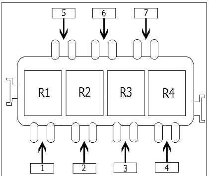
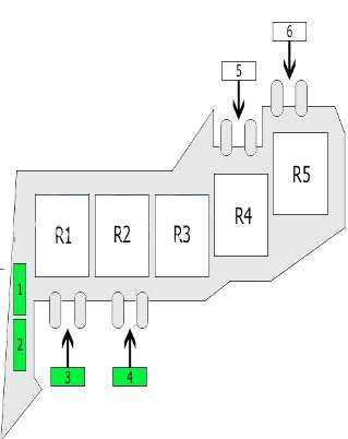
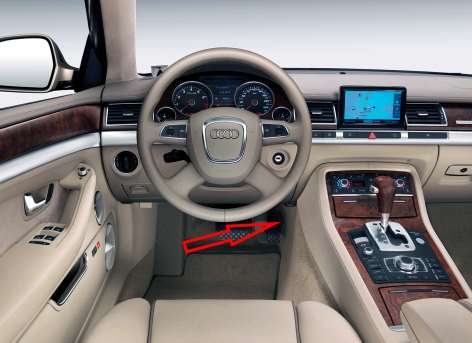
In the engine compartment
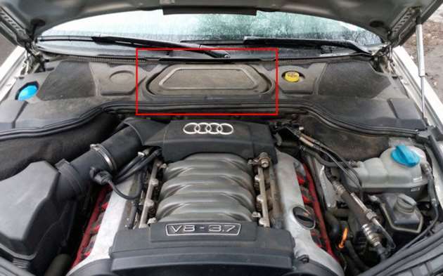
It is located in the center of the engine compartment behind the lining.
| Diagram | ||
|---|---|---|
|
||
| No. | Description | A |
| 1 | not used | |
| 2 | secondary air pump | 50/60/80 |
| Or | ||
| glow plug | ||
| 3 | secondary air pump | 50/60/80 |
| Or | ||
| glow plug | ||
| 4 | not used | |
| 5 | ||
| 6 | ||
| 7 | ||
| R1 | Glow plug relay | |
| Secondary air pump relay | ||
| R2 |
|
|
| R3 |
|
|
| R4 | not used | |
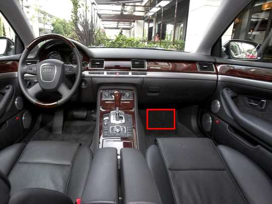
In the passenger compartment
There are two fuse distribution boxes and two relay boards here.
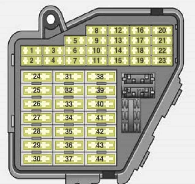
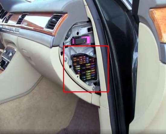
Fuse box #1
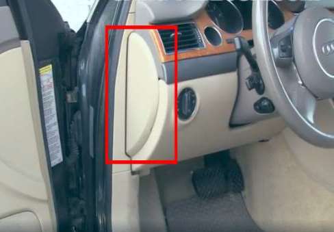
Located on the driver's side at the end of the dashboard behind a plastic cover.

General view.
| Diagram of the fuse box No. 1 on the driver's side | ||
|---|---|---|
|
||
| No. | A | Purpose |
| 1 | 5 | garage door opener (HomeLink) |
| 2 | 5 | parking assistance (acoustic parking system) |
| 3 | 5 | |
| 4 | 10 | automatic headlight beam throw adjustment |
| 5 | 5 | instrument cluster |
| 6 | 10 | steering column electronics control unit |
| 7 | 5 | diagnostic plug |
| 8 | 5 | |
| 9 | 5 | electronic stability program (ESP) |
| 10 | 5 | instrument cluster |
| 11 | - | is absent |
| 12 | 5 | brake light switch |
| 13 | 10 | telephone |
| 14 | - | is absent |
| 15 | 5 | driver identification system control unit |
| 16 | - | is absent |
| 17 | 5 | distance maintenance (adaptive cruise control) |
| 18 | 5 | heated windshield washer jets |
| 19 | - | is absent |
| 20 | 5 | tire pressure monitoring system |
| 21 | - | is absent |
| 22 | 5 | brake light switch |
| 23 | 5 | telepassport |
| 24 | 15 | sound signal |
| 25 | 40 | wiper |
| 26 | - | is absent |
| 27 | 25 | electronic stability program (ESP) |
| 28 | - | is absent |
| 29 | 10 | lighting switches |
| 30 | - | is absent |
| 31 | 30 | onboard power supply control unit, front right lighting |
| 32 | - | is absent |
| 33 | 25 | additional space heater for hoi rear left |
| 34 | - | is absent |
| 35 | - | is absent |
| 36 | - | is absent |
| 37 | - | is absent |
| 38 | 30 | onboard power supply control unit, lighting front left |
| 39 | 7.5 | front left door control unit |
| 40 | 25 | steering column adjustment |
| 41 | 7.5 | rear left door control unit |
| 42 | 25 | start identification/permission control unit |
| 43 | - | is absent |
| 44 | - | is absent |
Fuse box #2
Located on the passenger side behind a plastic cover.
| Assigment of fuses in the passenger side | ||
|---|---|---|

|
||
| No. | A | Description |
| 1 | 5 | electromechanical parking brake |
| 2 | 10 | air conditioning |
| 3 | 5 | shift gate, PN-lock |
| 4 | 15 | automatic transmission (multitronic) |
| 5 | 15 | engine management |
| 6 | 15 | lambda probes |
| 7 | 15/10 | lambda probes/high pressure valve |
| 8 | 10 | engine management, auxiliary water pump |
| 9 | 5 | air conditioning, instrument panel keys |
| 10 | 10 | air suspension (adaptive air suspension) |
| 11 | 5 | light and rain sensor |
| 12 | 5 | display/control unit front |
| 13 | 10 | electronics in the ceiling |
| 14 | 5 | media player in front (CD player, DVD player, etc.) |
| 15 | 5 | battery-energy management system |
| 16 | 5 | heating crankcase ventilation system |
| 17 | 5 | jura valve electronics |
| 18 | - | is absent |
| 19 | 5 | diesel air mass sensor |
| 20 | 5 | air-conditioned seat |
| 21 | 5/15 | engine management (gasoline/diesel) |
| 22 | 10 | fuel cooling |
| 23 | 5 | electromechanical parking brake |
| 24 | 10 | onboard power supply control unit 2 |
| 25 | 15 | automatic transmission |
| 26 | 10 | water pump/A/C valves, rear A/C controls |
| 27 | 20 | sliding roof panel |
| 28 | 5 | the engine control unit |
| 29 | 15 | Valve injectors |
| 30 | 30 | ignition coils |
| 31 | 20/40 | fuel pump right/fuel pump electronics (petrol) |
| 32 | 5/10) | automatic transmission/multitronic |
| 33 | 25 | additional heating gel legroom rear right |
| 34 | 20 | heated/ventilated rear seats |
| 35 | 20 | Heated/ventilated front seats |
| 36 | 20 | Front cigarette lighter audi a8 d4 |
| 37 | 20/30 | rear cigarette lighter and sockets |
| 38 | 20 | additional radiator fan |
| 39 | 7.5 | front right door control unit |
| 40 | 15 | brake booster |
| 41 | 7.5 | rear right door control unit |
| 42 | 20 | auxiliary heater/auxiliary heater |
| 43 | 30 | headlight cleaner |
| 44 | 30 | heater fan |
Relay box #1
Located behind the trim at the passenger's feet.
| Diagram | ||
|---|---|---|
|
||
| No. | Purpose | A |
| R1 |
|
|
| R2 | Starter relay | |
| R3 | ||
| R4 | Fuel pump relay | |
| Or | ||
| Power relay | ||
| R5 | Headlight washer relay | |
| 1 | Front right window lifter | 30 |
| Or | ||
| empty | ||
| 2 | Seat adjustment | 30 |
| 3 | blower | 30 |
| Or | ||
| Front right window lifter | ||
| Or | ||
| empty | ||
| 4 | Seat adjustment | 30 |
| 5 | not used | |
| 6 | ||
Relay box #2
Located behind the trim on the driver's side.
| Diagram | ||
|---|---|---|

|
||
| No. | Purpose | A |
| 1 | ABS control unit | 60 |
| 2 | Leveling system | 40 |
| 3 | Power window | 30/40 |
| 4 | Seat adjustment | 30 |
| 5 | 30 | |
| 6 | not used | |
| 7 | not used | |
| 8 | not used | |
| R1 | Adaptive Suspension Compressor Relay | |
| R2 | signal relay | |
| R3 | Terminal 15 supply voltage relay | |
| R4 | Washer heating relay | |
| R5 | Security system control unit (taxi) | |
| R6 | Terminal 75 supply voltage relay | |
| R7 | empty | |
| R8 | empty | |
| R9 | empty | |
| R10 | empty | |
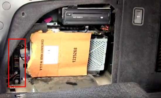
In the luggage compartment
There are two blocks here.
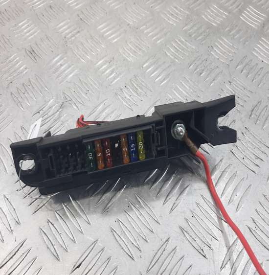
Fuse box #1
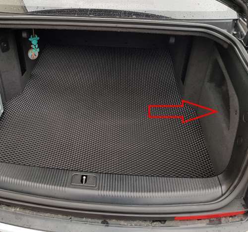
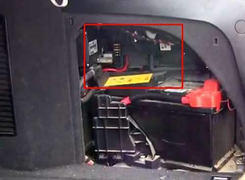
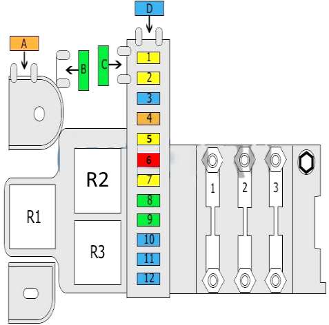
Block number 1 is on the right side behind the skin.
Access example.
General view.
| Diagram | ||
|---|---|---|
|
||
| No. | A | Description |
| 1 | 20 | fuel pump right (diesel) |
| 2 | 20 | fuel pump on the left (gasoline / diesel) |
| 3 | 15 | trailer socket |
| 4 | - | is absent |
| 5 | 20 | intelligent power module at the rear (light on the left) |
| 6 | 10 | intelligent power module at the rear (light on the right) |
| 7 | 20 | intelligent rear power module (trunk closing assist) |
| 8 | 30 | electromechanical parking brake, left motor |
| 9 | 30 | electromechanical parking brake, right motor |
| 10 | 15 | trailer control unit (light left) |
| 11 | 15 | trailer control unit (light on the right) |
| 12 | 10 | trailer control unit |
| A | 40 | Rear window heating |
| B | 30/40 | Rear seat adjustment |
| Or | ||
| Gasoline pump | ||
| C | 30 | Rear seat adjustment |
| D | 15 | Communication system |
| Or | ||
| Not used | ||
| R1 | Heated rear window relay | |
| R2 | Power relay | |
| R3 | Fuel pump relay | |
| 1 | 150 | Source of power |
| 2 | 60 | Radio |
| Navigation system | ||
| TV tuner | ||
| 3 | 110 | Rear window heating |
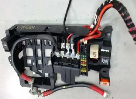
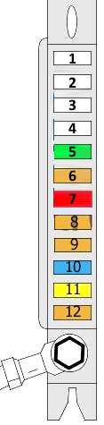
Fuse box #2
The second block located on the left side.
General view.
| Diagram | ||
|---|---|---|
|
||
| No. | A | Purpose |
| 1 | - | No |
| 2 | - | No |
| 3 | - | No |
| 4 | - | No |
| 5 | 30 | DSP amplifier |
| 6 | 5 | navigation |
| 7 | 10 | TV tuner |
| 8 | - | is absent |
| 9 | 5 | communication block |
| 10 | 15 | phone loudspeaker in hat rack |
| 11 | 20 | socket |
| 12 | 5 | auxiliary heater radio receiver |

i have a 2009 audi A8L d3 and im trying to find the fuse for the back up assistance camera. being that its a rear component id figure it would be in the luggage are fuse box but not sure which one as i haven't found a diagram with that fuse location. could you possibly help me with this
Engine bay image is for the climate controls air filter not relays and fuses
El cuadro de velocidad, revoluciones, se escucha un clip clip pero no funciona