The A8 is a luxury car manufactured by Audi AG in Neckarsulm, Germany, the successor to the V8. In this material, we will analyze in detail the fuse and relay circuits of the Audi A8 / S8 (body index 4H) of the 3rd generation 2010, 2011, 2012, 2013, 2014, 2015, 2016, 2017, 2018 model year with 2.0 TFSI Hybrid engines, 3.0 TDI, 3.0 TFSI, 4.0 FSI, 4.2 FSI, 4.2 TDI, 6.3 W12.
Here you will find the locations and photos of distribution boxes. The fuses responsible for the “Cigarette lighter” and “Fuel Pump” are highlighted in bold.
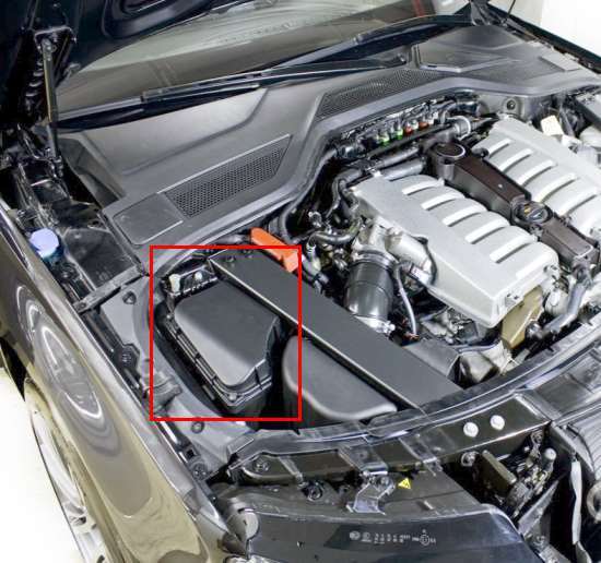
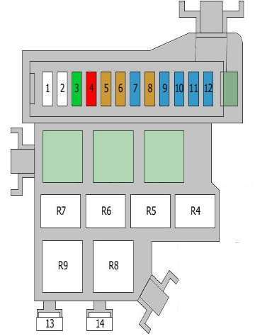
In the luggage compartment
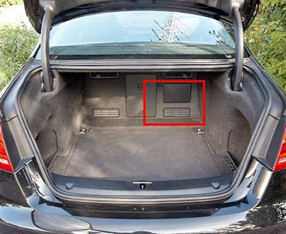
The block is behind a plastic cover.

Access example.
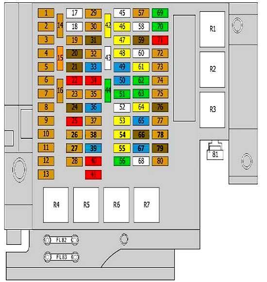
| Diagram | ||
|---|---|---|
|
||
| No. | Description | A |
| 1 | TCS/ESP button | 5 |
| Headlight range control unit | ||
| Power control unit | ||
| Diagnostic socket (16) | ||
| 2 | Data bus diagnostic interface | 5 |
| 3 | Adaptive Suspension Control Unit | 5 |
| 4 | Parking assistance control unit | 5 |
| 5 | Control unit, steering column electronics | 5 |
| 6 | Control block | 5 |
| 7 | Airbag control unit | 5 |
| Passenger side airbag deactivation indicator | ||
| "Seat occupied" recognition control unit | ||
| 8 | Garage door control unit | 5 |
| Night vision control unit | ||
| Air quality improvement control unit | ||
| Heated nozzles | ||
| 4WD control unit | ||
| 9 | Electromechanical parking brake control module | 5 |
| 10 | Trailer detection control unit | 5 |
| Fridge | ||
| Seat heating control unit | ||
| Automatic anti-glare rear view mirror | ||
| 11 | Active steering control unit | 5 |
| 12 | Box Lever Control Unit | 5 |
| 13 | Lane change assist control unit | 5 |
| 14 | The engine control unit | 5 |
| 15 | starter relay | 40 |
| 16 | Headlight range control unit | 5/10 |
| Left headlight power control unit | ||
| 17 | Seat belt pretensioner control unit | 25 |
| 18 | Seat belt pretensioner control unit | 25 |
| 19 | The engine control unit | 5 |
| 20 | Voltage regulators | 7.5 |
| 21 | Camera control unit | 7.5 |
| 22 | Right headlight power control unit | 10 |
| 23 | ABS control unit | 5 |
| Air conditioning compressor | ||
| 24 | Engine crankcase heater | 7.5 |
| Emergency stop relay | ||
| Voltage regulator(s) | ||
| Engine mount control unit | ||
| Sound control unit transmitted through the vehicle body structure | ||
| 25 | Adaptive cruise control | 10 |
| battery | ||
| 26 | Automatic transmission control unit | 5 |
| Automatic transmission control unit | ||
| Local area network (CAN) controller | ||
| 27 | Air quality sensor | 5 |
| Refrigerant pressure and temperature sensor | ||
| Humidity sender | ||
| 28 | Special equipment | 5 |
| 29 | Electric parking brake | 5 |
| 30 | Reserve | 5 |
| 31 | Door control unit, rear right | 7.5 |
| 32 | Fuel tank leakage control unit | 5 |
| Fuel tank pressure sensor | ||
| telephone | ||
| 33 | Climatronic control unit | 15 |
| 34 | Air conditioning control unit | 10 |
| 35 | Data bus diagnostic interface | 5 |
| 36 | Fridge | 15 |
| 37 | Interface for special functions | 5 |
| 38 | Phone adapter, Bluetooth handset | 5 |
| 39 | Engine mount control unit | 15 |
| 40 | Gear lever control unit | 10 |
| 41 | Comfort control unit | 10 |
| 42 | 20 | |
| 43 | Fuel pump control unit | 25 |
| 44 | Parking brake control unit | 30 |
| 45 | empty | |
| 46 | 12V socket | 20 |
| 47 | Rear cigarette lighter | 20 |
| Additional sockets 12V | ||
| 48 | Front cigarette lighter fuse | 20 |
| DC-AC converter with socket, 12 V - 230 V | ||
| 49 | Adaptive Suspension Control Unit | 15 |
| fifty | DC-AC converter with socket, 12 V - 230 V | 15 |
| 51 | Parking brake control unit | 30 |
| 52 | Seat heating control unit | 25 |
| Air conditioning control unit | ||
| Heated rear seat switch | ||
| 53 | Comfort control unit | 20 |
| 54 | Air conditioning fan control unit | 20 |
| 55 | Comfort control unit | 20 |
| 56 | Reserve | 30 |
| 57 | Rear seat adjustment | 5 |
| Seat remote control | ||
| 58 | Cooling Fan Relay | 35 |
| 59 | Seat adjustment | 7.5 |
| 60 | Trailer detection control unit | 25/30 |
| trailer connector connector | ||
| 61 | Trailer detection control unit | 20/25 |
| trailer connector connector | ||
| 62 | Seat adjustment | 30 |
| 63 | Seat adjustment | 30 |
| 64 | Trailer detection control unit | 20/25 |
| trailer connector connector | ||
| 65 | Trailer detection control unit | 15 |
| trailer connector connector | ||
| 66 | Seat adjustment | 7.5 |
| 67 | Accumulator battery | 15 |
| 68 | empty | - |
| 69 | Audio control unit | 30 |
| Voltage regulators | ||
| radio tape recorder | ||
| 70 | Audio control unit | 30 |
| 71 | multimedia control unit | 10 |
| Voltage regulators | ||
| Information display control unit | ||
| Information display | ||
| 72 | Tire pressure monitoring unit | 5 |
| 73 | Rear view camera control unit | 5 |
| Automatic anti-glare rear view mirror | ||
| 74 | DVD | 5 |
| 75 | TV tuner | 5 |
| 76 | Information display control unit | 7.5 |
| 77 | Control Panel | 5 |
| Analog clock | ||
| 78 | Vehicle information control unit | 5 |
| 79 | radio tape recorder | 7.5 |
| 80 | Telephone | 5 |
| Chip card reader | ||
| Rear view camera control unit | ||
| 81 | empty | - |
| 82 | Reserve | 80 |
| 83 | Reserve | 110 |
| 84 | Rear window heating | 40 |
| 85 | Leveling system | 40 |
| 86 | Engine start/stop switch | 40 |
| 87 | Front passenger seat adjustment | 15 |
| R1 | Adaptive Suspension Compressor Relay | |
| R2 | Rear window heating | |
| R3 | Automatic anti-glare rear view mirror | |
| Cooling Fan Relay | ||
| R4 | Fuel pump relay | |
| R5 | Engine starter relay | |
| R6 | Terminal 15 relay supply voltage | |
| R7 | Relay Power Socket | |
Auxilary fuse holder
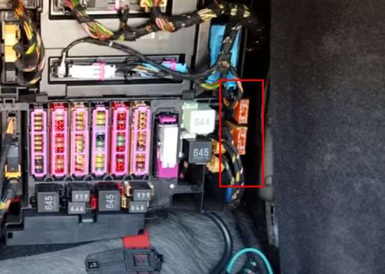
An additional fuse board is located next to the main unit.
| Diagram | ||
|---|---|---|

|
||
| 1 | reducer heater | 30 |
| 2 | reagent dosing system | 10 |
| R1 | reagent dosing system relay | |
In the passenger compartment
From the passenger's side
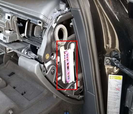
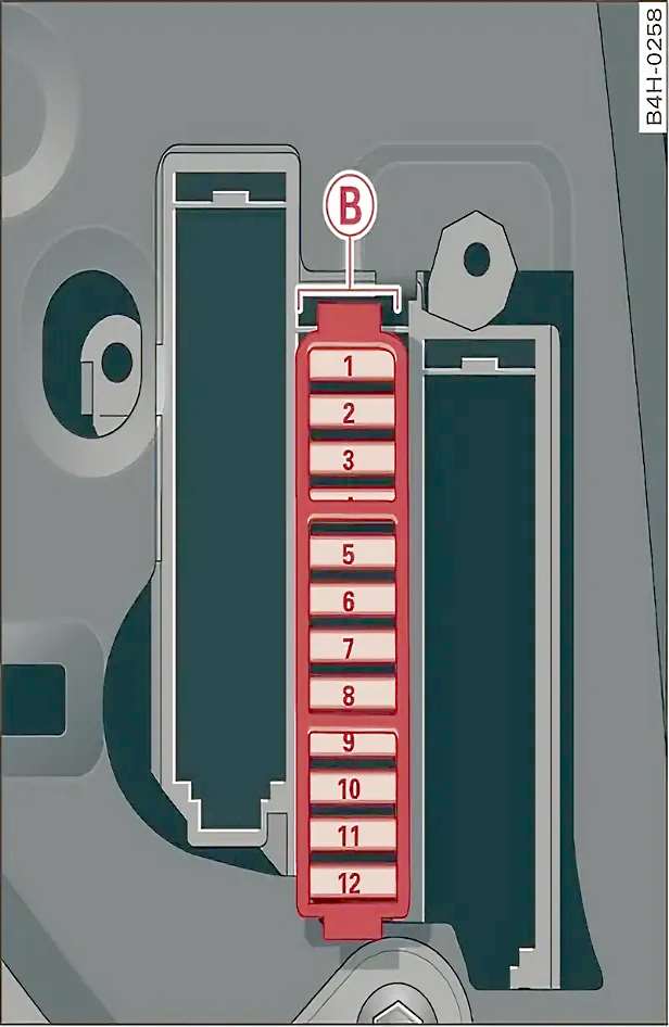
The first block is located at the end of the dashboard on the passenger side.
| Diagram | ||
|---|---|---|
|
||
| No. | Purpose | A |
| 1 | Anti-theft system | 5 |
| 2 | transmission control module | 15 |
| 3 | Front climate control fan | 40 |
| 4 | Engine power | 35 |
| 5 | empty | - |
| 6 | Engine control module | 5 |
| 7 | Control module (front right door) | 7.5 |
| 8 | Front passenger window | 30 |
| 9 | ESC control module | 10 |
| 10 | 25 | |
| 11 | Rear right power window | 30 |
| 12 | Front passenger seat (pneumatic) | 15 |
From the driver's side
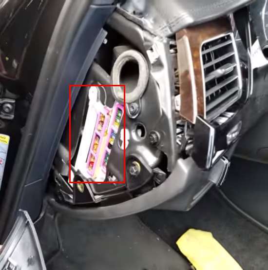
The second fuse box is located at the end of the dashboard on the driver's side.
| Diagram | ||
|---|---|---|
|
||
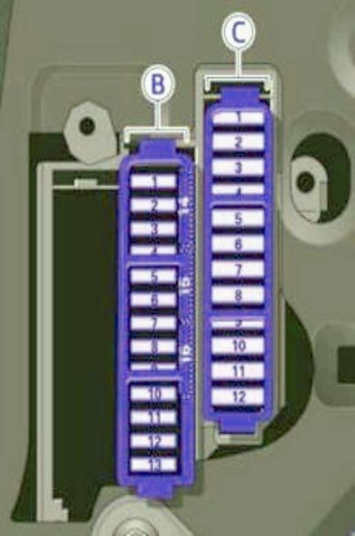
| Panel (B) | ||
| No. | Purpose | A |
| 1 | Headlight switch | 5 |
| 2 | Emergency start (ID key) | 5 |
| 3 | Control module (rear left door) | 7.5 |
| 5 | Sound signal | 15 |
| 6 | Interior lighting (ceiling) | 7.5 |
| 8 | Steering column handle, heated steering wheel, multi-steering wheel | 10/5 |
| 10 | Steering column adjustment | 5 |
| 11 | Control module (driver's door) | 7.5 |
| 12 | Diagnostic connector, light/rain sensor | ten |
| 14 | Steering column adjustment | 25 |
| 15 | Power steering, air conditioning compressor | 20 |
| 16 | brake booster | 15 |
| Panel (C) | ||
| 1 | Heated front seats | 30 |
| 2 | Wiper | 30 |
| 3 | Front exterior lighting | 30 |
| 4 | Sunroof | 20 |
| 5 | Driver window | 30 |
| 6 | Driver's seat (pneumatic) | 15 |
| 7 | panoramic sunroof | 20 |
| 8 | Dynamic Steering | 35 |
| 9 | Front exterior lighting | 30 |
| 10 | Windshield washer, headlight washer | 35 |
| 11 | Rear left power window | 30 |
| 12 | panoramic sunroof | 40 |
In the engine compartment
The main distribution box is located on the right side (in the direction of travel) behind the protective cover.
| Diagram | ||
|---|---|---|
|
||
| No. | Description | A |
| 1 | Mass air flow meter | 5 |
| 2 | empty | - |
| 3 | empty | - |
| 4 | The engine control unit | 15 |
| Engine control unit 2 | ||
| 5 | Cooling fan control unit | 5 |
| Fuel pump control unit | ||
| Fan | ||
| Fuel pump relay | ||
| 6 | brake light switch | 5 |
| 7 | Glow plug control unit | 10 |
| Electro-hydraulic left engine mount | ||
| Transmission mounting electromagnets | ||
| Transmission oil cooling valve | ||
| 8 | Oil level and temperature sensor | 5 |
| 9 | Transmission mounting electromagnets | 10 |
| Fuel pressure control valve | ||
| Fuel metering valve | ||
| 10 | oxygen sensors | 15 |
| 11 | Glow plug control unit | 15 |
| Right electro-hydraulic engine mount solenoid | ||
| Exhaust cooler valve | ||
| Oil pressure control valve | ||
| Coolant Bypass Valve | ||
| Special connector | ||
| Transmission mounting electromagnets | ||
| 12 | EGR coolant pump | 15 |
| coolant circulation pump | ||
| 13 | glow plug | 80 |
| 14 | glow plug | 50 |
| R8 | Glow plug control unit | |
| R9 | ||
Auxilary fuse holder
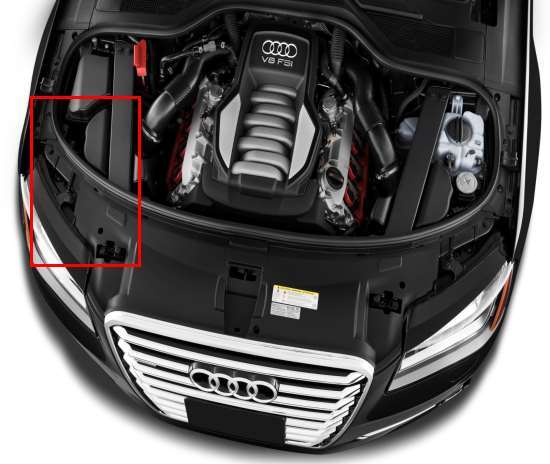
The additional holder is behind facing in front of a motor compartment.
| Diagram | ||
|---|---|---|
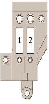
|
||
| No. | Purpose | A |
| 1 | Cooling Fan | 40/60 |
| 2 | 40/60 | |
