
In 2011, BMW officially introduced the sixth generation of the 3 Series premium vehicle line. The model range comprises the F30 sedan, the F31 Touring (station wagon), and the F34 Gran Turismo (fastback). This guide provides detailed power distribution diagrams and fuse box layouts for the BMW F30 / F31 / F80 3 Series (6th Gen; 316d, 316i, 318d, 318i, 320si, 320d, 323i, 325i, 328i, 330d, 330i, 335d, 335i, and Hybrid models) produced between 2011 and 2019.

Below you will find photos and layout diagrams for each power distribution panel, including the specific fuse position for the 12V power sockets and cigarette lighter.
Rear Luggage Compartment
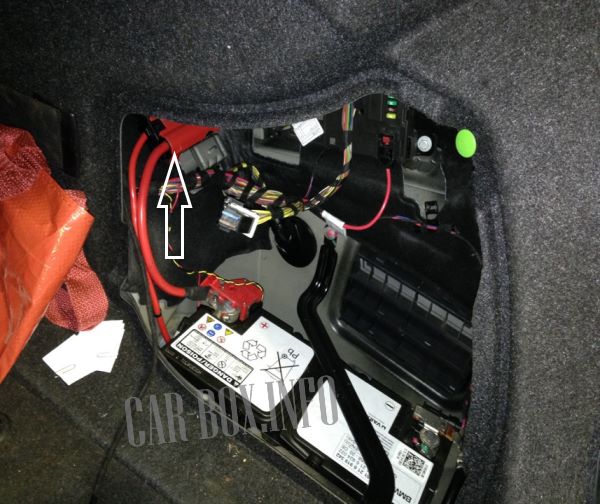
The high-current fusible links are positioned on the right side of the trunk panel, directly adjacent to the battery.
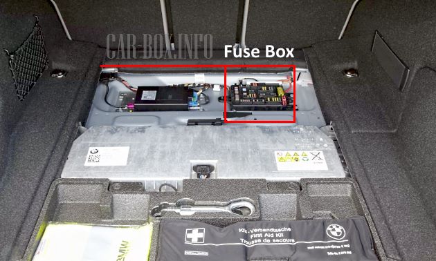
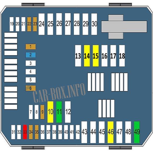
The primary rear fuse panel is mounted centrally beneath the luggage compartment floor panel.
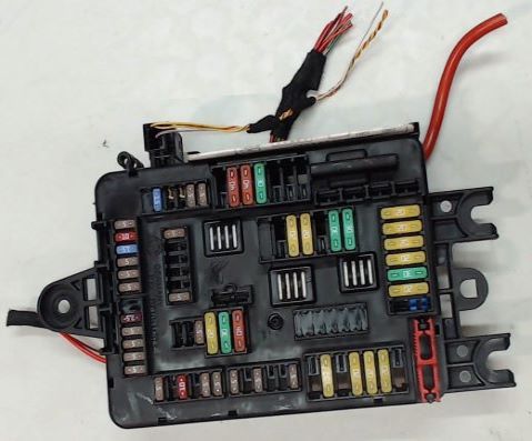
Example view of the primary rear power distribution panel.
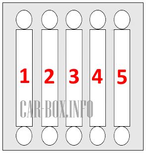
| High-Current Fuse Block Diagram (Battery-Mounted Panel) | ||
|---|---|---|
|
||
| No. | Protected Component / Function | Rating (A) |
| 1 | Rear Electronic Module (REM) | 50 |
| 2 | Primary Fuse Panel | 100 |
| 3 | Power Distribution Box | 100 |
| 4 | Main Relay | 125 |
| 5 | Integrated Power Supply Module | 125 |
| Rear Fuse Panel Assignment (Luggage Compartment) | ||
|---|---|---|
|
||
| No. | Protected Component / Function | Rating (A) |
| 1 | Camera System Control Module | 5 |
| 2 | Radio / Head Unit Control Module | 15 |
| 6 | Audio System | 5 |
| 9 | Telematics Control Unit (TCU) | 5 |
| 10 | Radio / Head Unit Control Module | 20 |
| 11 | Hi-Fi Audio Amplifier | 30 |
| 14 | Trailer Hitch Module (AHM) | 20 |
| 15 | 20 | |
| 22 | Anti-Theft Alarm System (DWA) | 5 |
| Interior Motion Sensor | ||
| 23 | Remote Control Receiver | 5 |
| Evaporative System Leak Detection (NVLD) | ||
| 33 | Audio System | 10 |
| 34 | DVD Player | 5 |
| 35 | Unused | 5 |
| 46 | Bus Terminating Resistor | 20 |
| 49 | DC-DC Converter | 30 |
Passenger Compartment
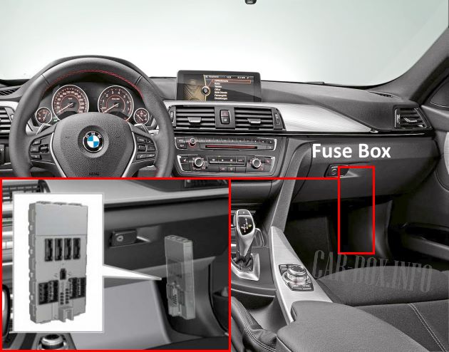
The interior junction box / Front Electronic Module (FEM) is located on the passenger side, mounted near the footwell kick panel behind the glove box area.

General view of the BMW F30 / F31 / F80 interior fuse module.
| Interior Fuse Box Diagram | ||
|---|---|---|

|
||
| No. | Protected Component / Function | Rating (A) |
| 1 | Unused | - |
| 2 | Unused | - |
| 3 | Unused | - |
| 4 | Front Passenger Power Window Switch | 30 |
| 5 | Central Locking System | 20 |
| 6 | Driver Power Window Switch | 30 |
| 7 | Unused | - |
| 8 | Unused | - |
| 9 | Unused | - |
| 10 | Center Console Switch Panel | 5 |
| Driver Assistance Systems | ||
| HVAC Control Unit | ||
| Headlight Switch Module | ||
| 11 | Rear Electronic Module (REM) | 7.5 |
| Left Headlight Assembly | ||
| 12 | OBD-II Diagnostic Connector | 7.5 |
| 13 | Telematics Control Unit | 5 |
| 14 | Dual Horn System | 15 |
Engine Compartment
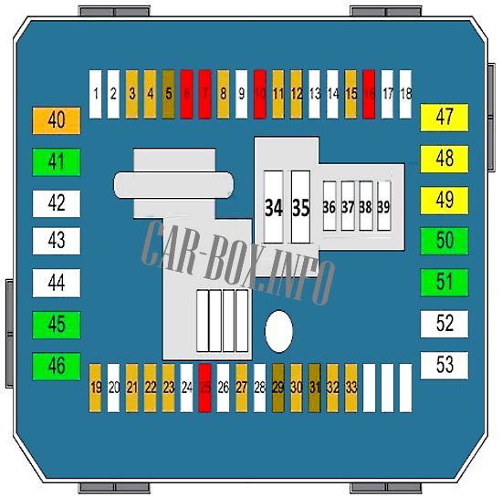
The engine bay houses four power distribution and protection units serving the powertrain and vehicle electronics.
Main Engine Compartment Fuse Box
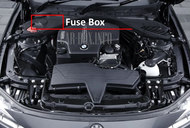
The primary engine bay distribution panel is located on the right side of the engine compartment near the windshield cowl. Access requires removing the plastic cowl trim panel fasteners. Supplementary relays and high-current fuses are mounted adjacent to this box.

Cowl panel removal and access procedure.
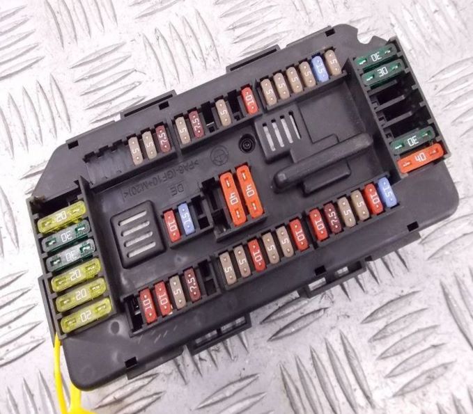
General view of the main engine compartment distribution box.
| Engine Compartment Main Fuse Box Diagram | ||
|---|---|---|
|
||
| No. | Protected Component / Function | Rating (A) |
| 1 | Unused | - |
| 2 | Unused | - |
| 3 | Roof Function Center (FZD) | 5 |
| 4 | HVAC Control Module | 5 |
| 5 | Power Door Locks | 7.5 |
| Passenger Exterior Mirror Assembly | ||
| 6 | DME / DDE Engine Electronics Main Relay | 10 |
| 7 | Electronic Transmission Control (EGS) Module | 10 |
| 8 | iDrive Touch Controller Module | 5 |
| Front Electronic Module (FEM) | ||
| 9 | Unused | - |
| 10 | Power Seat Adjustment Module | 10 |
| 11 | Left Headlight Control Module | 5 |
| Right Headlight Control Module | ||
| Rain / Light / Solar Sensor | ||
| Unused | ||
| 12 | Terminal 15 (Ignition Power) Relay | 5 |
| Dynamic Stability Control (DSC) Module | ||
| 13 | Unused | - |
| 14 | Unused | - |
| 15 | All-Wheel Drive / Transfer Case Control Module (VTG) | 5 |
| 16 | Electric Coolant Pump | 10 |
| A/C Compressor Clutch Control | ||
| Auxiliary Water Pump | ||
| 17 | Unused | - |
| 18 | Unused | - |
| 19 | Electrochromic Auto-Dimming Rearview Mirror | 5 |
| 20 | Unused | - |
| 21 | Driver Assistance Systems Module | 5 |
| 22 | Dynamic Cruise Control System | 5 |
| 23 | Crankcase Ventilation / PCV Heating Element | 5 |
| Coolant Shut-Off Valve | ||
| 24 | Unused | - |
| 25 | Steering Column Switch Cluster (SZL) | 10 |
| 26 | Unused | - |
| 27 | Instrument Cluster (KOMBI) | 5 |
| 28 | Unused | - |
| 29 | Instrument Cluster (KOMBI) | 7.5 |
| 30 | Glove Box Light Assembly | 5 |
| 31 | Gear Selector Lever Switch (GWS) | 7.5 |
| 32 | Electronic Power Steering (EPS) System | 5 |
| 33 | Automatic Air Recirculation Control (AUC) Sensor | 5 |
| 34 | Unused | - |
| 35 | Unused | - |
| 36 | Unused | - |
| 37 | Unused | - |
| 38 | Unused | - |
| 39 | Unused | - |
| 40 | Auxiliary Fuse Block Power Feed | 40 |
| 41 | Dynamic Stability Control (DSC) System | 30 |
| 42 | Unused | - |
| 43 | Unused | - |
| 44 | Unused | - |
| 45 | Convertible Soft-Top Control Module | 30 |
| 46 | Transfer Case Control Module (VTG) | 30 |
| 47 | Front Passenger Heated Seat Controller | 20 |
| 48 | Driver Heated Seat Controller | 20 |
| 49 | BMW F30 / F31 / F80 12V Accessory Outlet / Cigarette Lighter Fuse | 20 |
| 50 | Driver Power Seat Control Module | 30 |
| Driver Power Seat Adjustment Motors | ||
| 51 | Front Passenger Power Seat Adjustment Motors | 30 |
| Front Passenger Power Seat Control Module | ||
| 52 | 12V Power Socket Network | - |
| 53 | Unused | - |
High-Current Fusible Links
Located immediately adjacent to the main engine compartment fuse panel.
| Engine Bay High-Current Fuse Diagram | ||
|---|---|---|

|
||
| No. | Protected Component / Function | Rating (A) |
| 1 | Battery Safety Terminal (BST) / Power Disconnect Relay | 50 80 125 |
| 2 | Electronic Power Steering (EPS) Motor | 125 |
| 3 | Auxiliary Electric Cabin Heater | 100 |
| 4 | Fuel Filter Heating Element | 40 |
| 5 | Dynamic Stability Control (DSC) Pump Unit | 40 |
| 6 | HVAC Blower Motor Assembly | 40 |
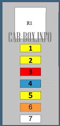
Auxiliary Fuse Panel 1
Mounted adjacent to the primary engine bay distribution panel.
| Auxiliary Fuse Panel 1 Diagram | ||
|---|---|---|
|
||
| No. | Protected Component / Function | Rating (A) |
| 1 | Engine Control Electronics (DME / DDE Power Supply) | 20 |
| 2 | 20 | |
| 3 | 10 | |
| 4 | 15 | |
| 5 | 20 | |
| 6 | 40 | |
| 7 | Primary Electric Coolant Pump | 50 |
| R1 | DME / DDE Main Engine Relay | |
Auxiliary Fuse Panel 2
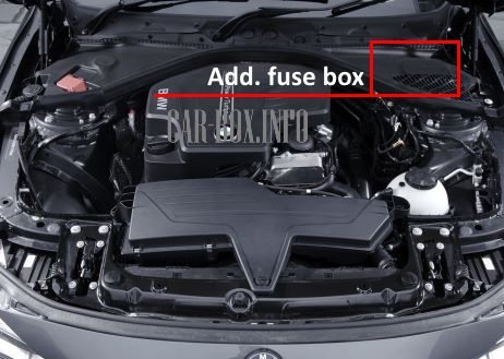
Located on the driver side (left side) of the engine compartment.
| Auxiliary Fuse Panel 2 Diagram | ||
|---|---|---|

|
||
| No. | Protected Component / Function | Rating (A) |
| 1 | Fuel Rail Pressure Control Valve | 20 |
| Fuel Metering / Volume Control Valve | ||
| Camshaft Position Sensors | ||
| Turbocharger Wastegate / Boost Pressure Actuator Solenoid | ||
| 2 | Pre-Cat Oxygen Sensor (Upstream) | 20 |
| Post-Cat Oxygen Sensors (Downstream) | ||
| Mass Air Flow (MAF) Sensor | ||
| Engine Oil Level / Temperature Sensor | ||
| EGR Cooler Changeover Switch Valve | ||
| 3 | Digital Diesel Electronics (DDE) Control Module | 30 |
| R1 | DME / DDE Main Engine Relay | |

So which one is for the battery and alternator?