The fifth generation BMW 3 Series was launched in March 2005. It is based on the platform on which BMW X3 and BMW 1-Series are built. The car is available in sedan (E90), station wagon (E91), coupe (E92) and convertible (E93). In this article, we will take a detailed look at the fuse box diagrams for the BMW e90 / e91 3-Series (5th Gen; 316d, 316i, 318d, 318i, 320si, 320d, 323i, 325i, 328i, 330d, 330i, 335d, 335i, M3) 2005, 2006, 2007, 2008, 2009, 2009, 2010, 2011, 2012, 2013 years of manufacture.
Here you will find the locations and photos of distribution boxes. The fuses responsible for the “Cigarette lighter” and “Fuel Pump” are highlighted in bold.
In the engine compartment
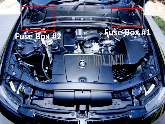
Depending on the equipment, there may be several units located in the underhood space. To access them, it is necessary to remove the cladding, having previously unscrewed the fixing screws.
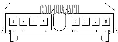
Power fuse box #1
Located near the battery.
| Diagram | ||
|---|---|---|
|
||
| No. | Decryption | A |
| 1 | Fuse box in the cabin | 250 |
| 2 | Launch system | 100 |
| 3 | power steering | 100 |
| 4 | Additional heater | 100 |
| 5 | Battery sensor | 100 |
| 6 | Additional heater | 100 |
| 7 | empty | - |
| 8 | Fuse box in the cabin | 250 |
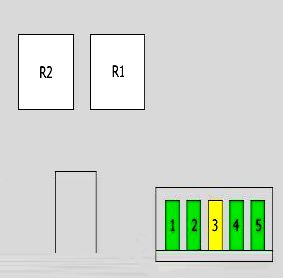
Fuse box #2
Located on the left side.
| Diagram | ||
|---|---|---|
| Type 1 | ||
|
||
| No. | Purpose | A |
| 1 | Fuel-air mixture sensor | 30 |
| Canister purge valve | ||
| Oil level sensor | ||
| 2 | Oxygen sensors behind and before the catalytic converter | 30 |
| 3 | crankshaft position sensor | 20 |
| Camshaft sensor | ||
| Electronics box (E-box), cooling fan | ||
| Fuse box in the cabin | ||
| fuel injectors | ||
| 4 | Canister Purge Valves | 30 |
| Engine control unit (DME) | ||
| 5 | energy saving relay | 30 |
| Terminal 15 | ||
| R1 | DME relay | |
| R2 | Energy saving relay | |
| Terminal 15 | ||
| Type 2 | ||

|
||
| No. | Description | A |
| 1 | Supercharger pressure regulator valve | 20 |
| Camshaft sensor | ||
| Ramp pressure control valve | ||
| Fuel control valve | ||
| Throttle position valve | ||
| 2 | EGR | 20 |
| Exhaust cooler valve | ||
| Mass flow meter | ||
| oxygen sensor | ||
| Oil quality sensor | ||
| Heating unit | ||
| 3 | The engine control unit | 30 |
| 4 | Electronic box (E-box) cooling fan | 10 |
| crankcase heater | ||
| radiator | ||
| 5 | Not | - |
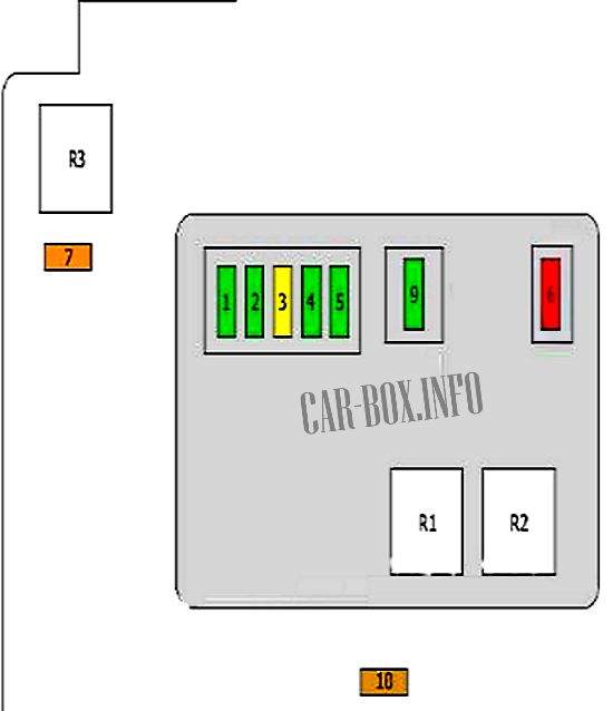
| Type 3 | ||
|
||
| No. | Purpose | A |
| 1 | Ignition coils 1 - 6 | 30 |
| 2 | coolant pump | 30 |
| MAP-controlled engine cooling thermostat | ||
| Canister purge solenoids | ||
| Camshaft sensor | ||
| 3 | Canister Purge Solenoid | 20 |
| Engine control unit (DME) | ||
| Mass flow meter | ||
| Oil level sensor | ||
| crankshaft position sensor | ||
| 4 | Oxygen sensors before and after the catalytic converter | 30 |
| crankcase ventilation | ||
| 5 | Injectors | 30 |
| 6 | Exhaust manifold cover | 10 |
| Electronics box (E-box) cooling fan | ||
| Fuel Tank Leak Diagnosis | ||
| Hot film air mass sensor | ||
| 7 | Valve timing relay | 40 |
| 9 | coolant pump | 30 |
| 10 | coolant heater relay | 5 |
| R1 | DME relay | |
| R2 | fuel injector | |
| R3 | Valve timing relay | |
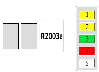
| Type 4 | ||
|
||
| No. | Decryption | A |
| 1 | Supercharger pressure sensor | 20 |
| Hall Sensor | ||
| Ramp pressure control valve | ||
| Canister purge valves, volume control | ||
| 2 | Oxygen sensor before catalytic converter | 20 |
| crankcase ventilation | ||
| EGR cooler changeover valve | ||
| Swirl solenoid valve | ||
| Heating control unit | ||
| Oil level sensor | ||
| 3 | The engine control unit | 30 |
| 4 | Electronic box (E-box), cooling fan | 10 |
| 5 | Not | - |
| R2003a | Main relay DDE | |
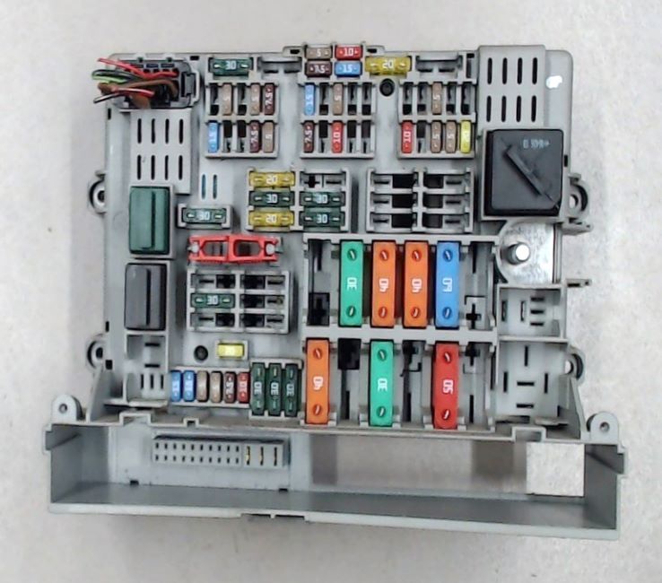
In the passenger compartment
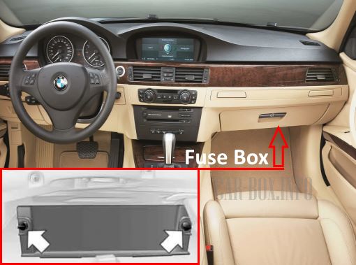
The distribution box is located in the glove compartment. To access it, unscrew the clips and remove the cover. It has several variations.
General view of the BMW E90 / E91 interior fuse box.
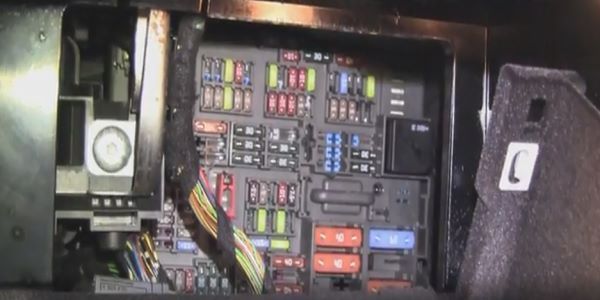
Access example.
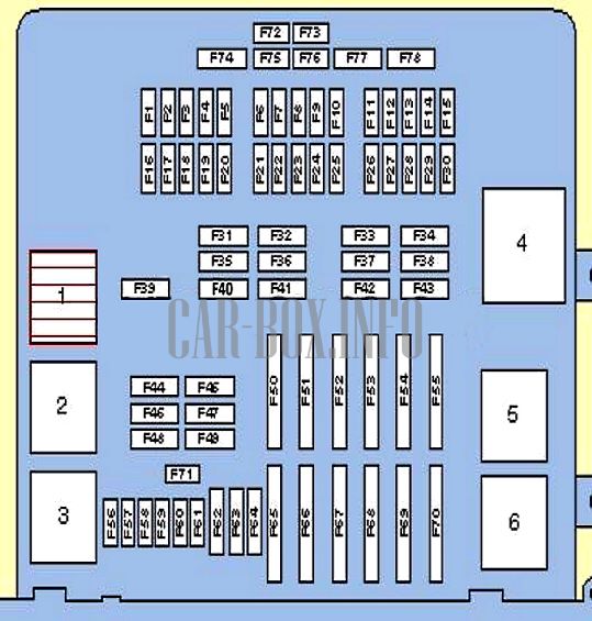
Type 1
Diagram.
|
||
| No. | Decryption | A |
| F1 | ^08/05: Electronic transmission control unit | 15 |
| F2 | Antenna selection control unit | 5 |
| F3 | empty | - |
| F4 | Ignition lock control unit | 5 |
| F5 | Sunroof | 7.5 |
| F6 | Electronic transmission control unit | 15 |
| F7 | Additional heater control unit | 20 |
| F8 | CD changer | 5 |
| F9 | Keeping distance (cruise control) | 10 |
| F10 | Towing unit folding mechanism | 15 |
| F11 | Audio system | 10 |
| F12 | Sunroof control | 20/15 |
| or | ||
| Transmission | ||
| F13 | CAN controller | 5 |
| F14 | empty | — |
| F15 | empty | — |
| F16 | Horn | 15 |
| F17 | empty | — |
| F18 | CD changer | 5 |
| F19 | Siren | 7.5 |
| Alarm system | ||
| Access control unit | ||
| Front door control unit | ||
| F20 | Transfer case control unit (if installed) | 5 |
| Dynamic Stability Control (DSC) | ||
| F21 | Passenger side mirror | 7.5 |
| Instrument panel | ||
| F22 | Distance Control Unit (Cruise Control) | 10 |
| F23 | Dynamic Stability Control (DSC) | 10 |
| Coupling device | 10 | |
| F24 | Tire pressure monitoring control unit | 5 |
| F25 | Spare | 10 |
| F26 | Telematics 90 | 10 |
| F27 | phone | 5 |
| dashboard | 5 | |
| auxiliary connector | 5 | |
| F28 | Parking control | 5 |
| Hatch control | 5 | |
| F29 | Heated front seats | 5 |
| Climate control | 5 | |
| F30 | bmw 3 E90 / E91 front cigarette lighter fuse | 20 |
| Rear 12V power outlet | 20 | |
| 12V socket in the trunk | 20 | |
| F31 | ^08/05: ABS system | 30 |
| F32 | Front left seat | 30 |
| Driver's seat heating | 30 | |
| F33 | Power front seats | 30 |
| F34 | Audio output amplifier | 30 |
| F35 | ^08/05: Engine management | 20 |
| F36 | Footwell electronics control unit | 30 |
| F37 | Power front seats | 30 |
| F38 | Spare | 30 |
| F39 | windshield wiper | 30 |
| F40 | Radio and navigation box | 20 |
| or | 20 | |
| fuel pump fuse | 20 | |
| F41 | footwell electronics | 30 |
| F42 | Power driver's seat | 30 |
| F43 | Headlight washers | 30 |
| F44 | Trailer control unit | 30 |
| F45 | trailer control unit | 20 |
| F46 | Rear window heater | 30 |
| F47 | trailer control unit | 20 |
| F48 | empty | — |
| F49 | Front seat heater | 30 |
| F50 | Spare | 40 |
| F51 | Ignition lock control unit | 50 |
| F52 | Footwell electronics control unit | 50 |
| F53 | 50 | |
| F54 | Engine management | 60 |
| F55 | empty | - |
| F56 | Bmw 90 central locking system | 15 |
| F57 | 15 | |
| F58 | Diagnostic connector | 5 |
| instrument panel | 5 | |
| F59 | Steering column electrical control unit | 5 |
| F60 | A/C ECU | 7.5 |
| F61 | Trunk illumination | 10 |
| Glove box illumination | 10 | |
| Information display | 10 | |
| F62 | Power windows rear | 30 |
| F63 | Spare | 30 |
| F64 | Power windows rear | 30 |
| F65 | ABS system | 40 |
| F66 | Fuel heating | 50 |
| F67 | air conditioner/heater fan motor | 50 |
| F68 | empty | - |
| F69 | Cooling fan motor | 50 |
| F70 | Spare | - |
| F71 | - | |
| F72 | - | |
| F73 | - | |
| F74 | - | |
| F75 | - | |
| F76 | - | |
| F77 | - | |
| F78 | - | |
| No. | Relay assignment | |
| R1 | windshield wiper motor | |
| R2 | rear window heating | |
| R3 | rear window cleaner | |
| R4 | Terminal 30 relay | |
| R5 | headlight washer pump | |
| R6 | exhaust air pump | |
| R7 | Horn | |
| R8 | fuel pump relay | |
| R9 | Terminal 15 relay | |
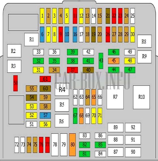
Type 2
Diagram (models until 2008).
|
||
| No. | Decryption | A |
| R1 | Rear Wiper Relay | |
| R2 | Wiper relay | |
| R3 | ||
| R4 | Terminal 15 relay | |
| Protection of cabin fuse circuits No.: 6, 7, 9, 10, 30, relay R6 | ||
| R5 | fuel pump relay | |
| R6 | horn relay | |
| R7 | Rear window heating | |
| R8 | Terminal 30 relay | |
| Protection of fuse circuits in the passenger compartment no: 13 - 15, 18 - 20, 22, 23, 25 - 28, 34, 45 46, 49, 60, 70, 71, 76, 77 | ||
| R9 | Junction box | |
| Protection of fuse circuits in the passenger compartment No.: 32, 56, 59, 61, 74 | ||
| R10 | Reserve | |
| 1 | Cleaner / washer | 20 |
| 2 | instrument cluster | 5 |
| Diagnostic connector | ||
| 3 | Passenger seat heating control unit | 20 |
| 4 | Vehicle access control unit | 5 |
| 5 | Fuel module relay (fuel pump) | 20 |
| 6 | Transmission | 15 |
| 7 | Additional heater | 20 |
| 8 | Amplifier | 15 |
| 9 | Cruise control | 10 |
| 10 | Trailer towing module | 15 |
| 11 | Radio | 10 |
| 12 | sunroof | 20 |
| 13 | Tire pressure monitoring unit | 5 |
| 14 | empty | — |
| 15 | Supply air / recirculation air drive | 5 |
| 16 | Signal | 15 |
| 17 | empty | — |
| 18 | Fresh / recirculation air drive | 5 |
| 19 | Signaling | 7.5 |
| 20 | Dynamic Stability Control (DSC) / Transfer case control unit | 5 |
| 21 | Passenger side mirror | 7.5 |
| 22 | dynamic drive | 10 |
| 23 | video system | 10 |
| 24 | DC converter | 5 |
| Fan | ||
| 25 | empty | — |
| 26 | Eject box | 10 |
| 27 | Phone | 10 |
| 28 | Parktronic | 5 |
| Sunroof | ||
| 29 | Heated front seats | 5 |
| 30 | 12V socket, cigarette lighter fuse bmw e90 | 20 |
| 31 | navigation | 20 |
| 32 | Seat adjustment, left side | 30 |
| 33 | Comfort access control unit | 40 |
| 34 | CD changer | 5 |
| or | ||
| Cabin fan | ||
| 35 | Dynamic Stability Control (DSC) | 30 |
| 36 | Spare | 30 |
| 37 | power seats | 10 |
| 38 | Transfer box control unit | 30 |
| 39 | wiper relay | 30 |
| 40 | Sunroof | 7.5 |
| 41 | Footwell control unit | 30 |
| 42 | 40 | |
| 43 | headlight washer module | 30 |
| 44 | trailer control unit | 30 |
| 45 | Steering | 40 |
| 46 | Seat adjustment, left side | 30 |
| 47 | Rear wiper and rear window de-icer | 30 |
| 48 | Windshield wiper/windshield washer | 20 |
| 49 | Seat adjustment, right side | 30 |
| 50 | The engine control unit | 10 |
| 51 | Vehicle access control unit | 50 |
| 52 | Heated driver's seat | 20 |
| 53 | Heated front passenger seats | 20 |
| 54 | Trailer | 7.5 |
| 55 | Vehicle access control unit | 5 |
| 56 | Navigation | 20 |
| 57 | Horn (beep) | 15 |
| 58 | instrument cluster | 5 |
| Diagnostic connector | ||
| 59 | Steering column | 5 |
| 60 | Multifunction display | 7.5 |
| 61 | Interior lighting | 10 |
| Air conditioner | ||
| Luggage compartment lighting | ||
| 62 | empty | — |
| 63 | empty | — |
| 64 | Additional connector | 5 |
| 65 | Dynamic Stability Control (DSC) | 40 |
| 66 | empty | — |
| 67 | washer | 30 |
| 68 | empty | 40 |
| 69 | Cooling fan (also used 60A) | 50 |
| 70 | Fuel pump control relay | 20 |
| 71 | Trailer | 20 |
| 72 | empty | — |
| 73 | empty | — |
| 74 | instrument cluster | 5 |
| 75 | Steering column | 5 |
| 76 | Multifunction display | 10 |
| 77 | Interior lighting(s) | 10 |
| Air conditioner | ||
| Luggage compartment lighting | ||
| 78 | empty | — |
| 79 | empty | — |
| 80 | Fuel heater | 40 |
| 81 | Trailer | 30 |
| 82 | Dynamic Stability Control (DSC) | 30 |
| 83 | empty | — |
| 84 | headlight washer pump | 40 |
| 85 | DC converter | 30 |
| 86 | Footwell control unit | 40 |
| 87 | empty | — |
| 88 | Fuel pump control | 20 |
| 89 | secondary air pump | 40 |
| 90 | Dynamic Stability Control (DSC) | 40 |
| 91 | empty | — |
| 92 | Cooling Fan | 60/50 |
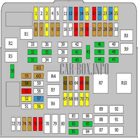
Diagram (models after 2008).
|
||
| No. | Description | A |
| R1 | Rear Wiper Relay | |
| R2 | Wiper relay | |
| R3 | ||
| R4 | Terminal 15 relay | |
| Fuse protection in cabin unit No.: 6, 7, 9, 10, 30, relay R6 | ||
| R5 | Fuel pump relay | |
| R6 | Signal | |
| R7 | Rear window heating | |
| R8 | Terminal 30 relay | |
| Fuse protection in the passenger compartment No.: 13 - 15, 18 - 20, 22, 23, 25 - 28, 34, 45, 46, 49, 60, 70, 71, 76, 77 | ||
| R9 | Junction box | |
| Protection of fuses in the passenger compartment No.: 32, 56, 59, 61, 74 | ||
| R10 | empty | |
| 1 | Cleaner / washer | 20 |
| 2 | Spare | — |
| 3 | Passenger seat heating control unit | 20 |
| 4 | Spare | — |
| 5 | Spare | — |
| 6 | Cabin air fan | 5 |
| DC-DC Converter | ||
| 7 | parking control | 5 |
| Retractable roof | ||
| 8 | 12V socket, cigarette lighter fuse | 20 |
| 9 | Phone | 5 |
| 10 | Heated front seats | 5 |
| 11 | Spare | |
| 12 | Vacuum pump | 15 |
| 13 | Eject box | 10 |
| 14 | radio tape recorder | 15 |
| 15 | Amplifier | 20 |
| 16 | Spare | — |
| 17 | Spare | — |
| 18 | video system | 10 |
| 19 | CD changer | 5 |
| 20 | power seats | 10 |
| 21 | Cruise control | 10 |
| 22 | Transmission | 15 |
| 23 | Additional air heater control unit | 20 |
| 24 | Trailer towing module | 15 |
| 25 | Sunroof | 20 |
| 26 | Dynamic Stability Control (DSC) / Transfer case control unit | 5 |
| 27 | Tire pressure monitoring unit | 5 |
| 28 | DC converter | 5 |
| Fan | ||
| 29 | Heated seats | 5 |
| 30 | Spare | — |
| 31 | Trailer | 30 |
| 32 | trailer control unit | 30 |
| 33 | fuel heater | 40 |
| 34 | Spare | — |
| 35 | Dynamic Stability Control (DSC) | 30 |
| 36 | Vehicle access control unit | 40 |
| 37 | Spare | — |
| 38 | Spare | — |
| 39 | Spare | — |
| 40 | Transfer box control unit | 30 |
| 41 | Footwell control unit | 30 |
| 42 | 40 | |
| 43 | headlight washer module | 30 |
| 44 | trailer control unit | 30 |
| 45 | Seat adjustment, right side | 30 |
| 46 | 30 | |
| 47 | Rear wiper and rear window de-icer | 30 |
| 48 | headlight washer | 30 |
| 49 | Steering | 40 |
| 50 | Wiper relay | 30 |
| 51 | Vehicle access control unit | 50 |
| 52 | Heated driver's seat | 20 |
| 53 | ARC | 10 |
| 54 | signaling | 7.5 |
| 55 | Vehicle access control unit | 5 |
| 56 | Navigation | 20 |
| 57 | Signal | 15 |
| 58 | Spare | — |
| 59 | Spare | — |
| 60 | Multifunction display | 5 |
| 61 | Comfort access control unit | 5 |
| remote control receiver | ||
| 62 | Sunroof | 7.5 |
| 63 | Cabin fan | 5 |
| 64 | Spare | — |
| 65 | Transmission | 10 |
| dynamic drive | ||
| 66 | Passenger side mirror | 7.5 |
| 67 | Fuel pump relay | 20 |
| 68 | Heated driver's seat | 20 |
| 69 | Cooling fan (also used 60A) | 50 |
| 70 | Fuel pump control relay | 20 |
| 71 | Trailer | 20 |
| 72 | Spare | — |
| 73 | Spare | — |
| 74 | instrument cluster | 5 |
| 75 | Steering column | 5 |
| 76 | Multifunction display | 10 |
| 77 | Interior lighting | 10 |
| Air conditioner | ||
| Luggage compartment lighting | ||
| 78 | Spare | — |
| 79 | Spare | — |
| 80 | Spare | — |
| 81 | Footwell control unit | 30 |
| 82 | Dynamic Stability Control (DSC) | 30 |
| 83 | Spare | — |
| 84 | Footwell control unit | 40 |
| 85 | DC converter | 30 |
| 86 | legroom management | 40 |
| 87 | Spare | — |
| 88 | washer | 40 |
| 89 | secondary air pump | 40 |
| 90 | Dynamic Stability Control (DSC) | 40 |
| 91 | Spare | — |
| 92 | Cooling Fan | 50 |
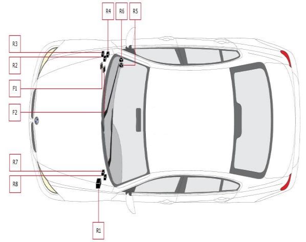
Additional relays
Their availability depends on the vehicle configuration.
| Diagram | |
|---|---|
|
|
| No. | Purpose |
| R1 | Main relay |
| R2 | Cooling Fan Relay |
| R3 | catalytic converter |
| R4 | Vacuum pump relay |
| R5 | Receiver Transmitter |
| R6 | Turn signal lamp relay |
| R7 | shutdown relay |
| R8 | Terminal 15 relay |
| F1 | Dynamic Stability Control (DSC) |
| F2 | |
