The BMW F20/F21 is the second generation of the 1 Series five-door compact hatchback. Like its predecessor, it has rear-wheel drive, longitudinal engine layout and 50:50 axle weight distribution. In this article, we will take a detailed look at the fuse box diagrams for the BMW 1 F20 / F21 (2nd Gen; 144d, 114i, 116d, 116i, 118d, 118i, 120d, 120i, 123d, 125i, 130i, 135i, m135i) 2011, 2012, 2013, 2014, 2015, 2016, 2017, 2017, 2018, 2019, 2020 years of manufacture.

Here you will find the locations and photos of distribution boxes. Also, we will separately mark the fuse responsible for the cigarette lighter.
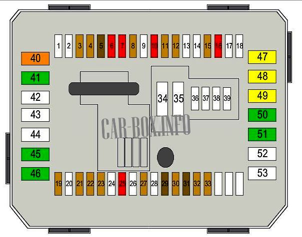
In the passenger compartment
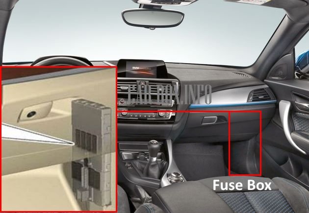
The distribution box is located on the passenger side under the right pillar trim.
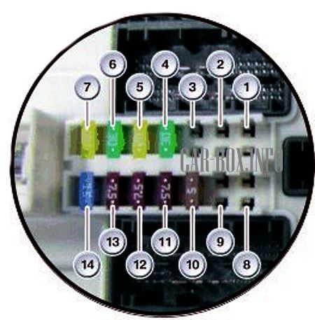
General view of the BMW 1 F20 / F21 interior fuse box.
| Diagram | ||
|---|---|---|
|
||
| No. | Decryption | A |
| 1 | Spare | — |
| 2 | Spare | — |
| 3 | Spare | — |
| 4 | Electric drive of the passenger seat | 30 |
| 5 | central locking system | 20 |
| 6 | Driver's window elevator | 30 |
| 7 | Spare | |
| 8 | Spare | — |
| 9 | Spare | — |
| 10 | Control Panel | 5 |
| Driver assistance system | ||
| Heating, ventilation and air conditioning (HVAC) | ||
| Light switch | ||
| 11 | Rear module | 7.5 |
| Left headlight | ||
| 12 | Diagnostic socket | 7.5 |
| 13 | Telematics | 5 |
| 14 | Horn (beep) | 15 |
In the trunk
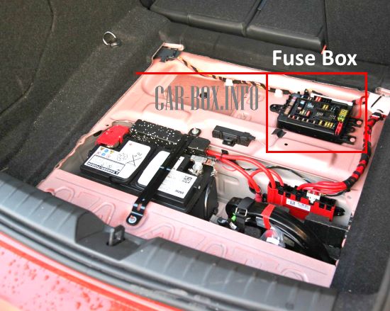
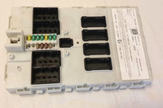
The distribution box is located on the right side under the floor, near the battery.

General view of the fuse box located in the trunk.
| Diagram | ||
|---|---|---|
|
||
| No. | Decryption | A |
| 1 | Camera control unit | 5 |
| 2 | Radio control unit | 15 |
| 6 | Audio system | 5 |
| 9 | telematics | 5 |
| 10 | Radio control unit | 20 |
| 11 | hi-fi amplifier | 30 |
| 14 | Trailer towing module | 20 |
| 15 | 20 | |
| 22 | Alarm system | 5 |
| Microwave sensor | ||
| 23 | remote control receiver | 5 |
| Vacuum leak detection | ||
| 33 | Audio system | 10 |
| 34 | DVD player | 5 |
| 35 | Main board | 5 |
| 46 | End connector | 20 |
| 49 | DC-DC Converter | 30 |
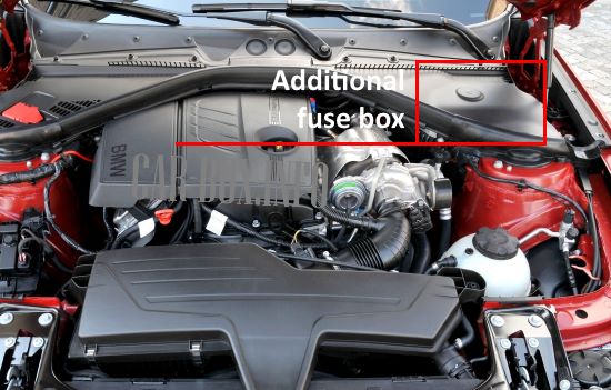
In the engine compartment
Here there are four units responsible for the protection of the vehicle's electrical circuits.
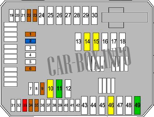
The main unit
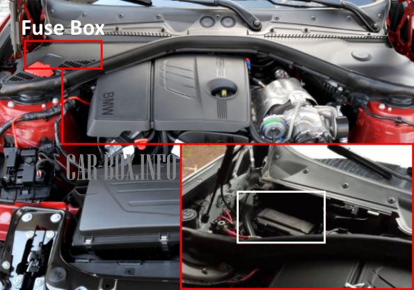
It is located under the plastic cover on the right side (left side on right-hand drive models). There is an additional relay block and a power board with fusible links.

General view.
| Diagram | ||
|---|---|---|
|
||
| No. | Decryption | A |
| 1 | Empty | — |
| 2 | Empty | — |
| 3 | Control unit, roof electronics | 5 |
| 4 | Empty | — |
| 5 | Door locks | 7.5 |
| Passenger-side rearview mirror | ||
| 6 | The engine control unit | 10 |
| 7 | Electronic automatic transmission (EAT) control unit | 10 |
| 8 | touch box | 5 |
| Body control unit | ||
| 9 | Empty | — |
| 10 | Seat adjustment | 10 |
| 11 | Front left lamp | 5 |
| Front right lamp | ||
| Rain sensor | ||
| Interior lighting | ||
| 12 | trip relay | 5 |
| Dynamic Stability Control (DSC) | ||
| 13 | Empty | — |
| 14 | Empty | — |
| 15 | transfer case | 5 |
| 16 | coolant pump | 10 |
| Air conditioning compressor | ||
| Additional water pump | ||
| 17 | Empty | |
| 18 | Empty | — |
| 19 | Electrochromic rear view mirror | 5 |
| 20 | Empty | — |
| 21 | Driver assistance system | 5 |
| 22 | Cruise control | 5 |
| 23 | Crankcase ventilation heater | 5 |
| Coolant shut-off valve | ||
| 24 | Empty | — |
| 25 | Steering column switches | 10 |
| 26 | Empty | — |
| 27 | instrument cluster | 5 |
| 28 | Empty | — |
| 29 | instrument cluster | 7.5 |
| 30 | Glove box illumination | 5 |
| 31 | Selector switch | 7.5 |
| 32 | Electronic Power Steering (EPS) | 5 |
| 33 | Air quality sensor | 5 |
| 34 39 |
Empty | — |
| 40 | Fuse box | 40 |
| 41 | Dynamic Stability Control (DSC) | 30 |
| 42 44 |
Empty | — |
| 45 | folding roof | 30 |
| 46 | transfer case | 30 |
| 47 | Passenger seat heating | 20 |
| 48 | Heated driver's seat | 20 |
| 49 | BMW f20 / f21 cigarette lighter fuse | 20 |
| 50 | Driver's seat control unit | 30 |
| Driver seat adjustment | ||
| 51 | Passenger seat adjustment | 30 |
| Passenger seat control unit | ||
| 52 | 12V power outlet | |
| 53 | Empty | — |
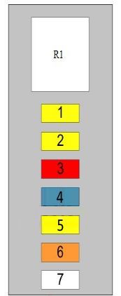
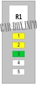
Additional unit #1
Located next to the main unit.
| Diagram | ||
|---|---|---|
|
||
| No. | Decryption | A |
| 1 | Engine management | 20 |
| 2 | 20 | |
| 3 | 10 | |
| 4 | 15 | |
| 5 | 20 | |
| 6 | 40 | |
| 7 | coolant pump | 50 |
| R1 | Main relay DDE | |
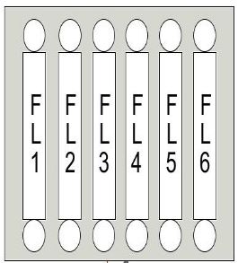
Power fusible links
The panel is located near the main fuse box.
| Diagram | ||
|---|---|---|
|
||
| No. | Description | A |
| FL1 | Trip relay | 50 80 125 |
| FL2 | Electronic Power Steering (EPS) | 125 |
| FL3 | Additional heater | 100 |
| FL4 | Heated fuel filter | 40 |
| FL5 | Dynamic Stability Control (DSC) | 40 |
| FL6 | blower motor | 40 |
Additional unit #2
Located on the left side of the engine compartment.
| Diagram | ||
|---|---|---|
|
||
| No. | Purpose | A |
| 1 | Ramp pressure control valve | 20 |
| Fuel volume regulator | ||
| Camshaft position sensor | ||
| Pressure regulator valve | ||
| 2 | Oxygen sensor before catalytic converter | 20 |
| Oxygen sensors behind the catalytic converter | ||
| Mass flow meter | ||
| Oil level sensor | ||
| EGR cooler switching valve | ||
| 3 | DDE control unit | 30 |
| R1 | Main relay DDE | |
