The BMW 1 Series is a line of compact cars that has been produced since 2004 in four body styles: 3-door and 5-door hatchback, coupe and 2-door convertible. In this article, we will take a detailed look at the fuse box diagrams for the BMW 1 e81 / e87 and e82 / e88 (1st generation: 116d, 116i, 118d, 118i, 120d, 120i, 123d, 125i, 130i, 135i, m1 coupe) 2004, 2005, 2006, 2007, 2008, 2008, 2009, 2009, 2010, 2010, 2011, 2012, 2013 years of manufacture.

Here you will find the locations and photos of distribution boxes. The fuses responsible for the “Cigarette lighter” and “Fuel Pump” are highlighted in bold.
All electrical equipment

General layout of the electrical system in the vehicle.
1. Air conditioning control module - behind the heater control panel;
2. Antenna selection control module - under the rear seat;
3. Antenna signal amplifier - telephone - left side of the luggage compartment;
4. Side impact sensor, driver's side - lower part of the center pillar;
5. Side impact sensor, passenger side - lower part of the center pillar;
6. Vehicle tilt sensor (anti-theft system)-in the anti-theft system horn.;
7. Anti-theft alarm system horn - behind the left rear wheel arch lining;
8. Volume change sensor (anti-theft system)-on the roof panel;
9. Audio system control module (DAB)-luggage compartment, under the floor.;
10. Audio output amplifier - left side of the luggage compartment;
11. Interference suppressor (audio system) - rear pillar;
12. Battery pack - under the luggage compartment floor;
13. Battery status sensor - on the battery;
14. Diagnostic connector;
15. Driver's door electrical control module;
16. Passenger door electrical control module;
17. Petrol pump control module (if fitted) - behind the right-hand support on the rear seat cushion;
18. Fuse box/relay box, dashboard - behind the duffel box;
19. Fuse box/relay, intake system resonator;
20. Fuse box/relay, battery (Valve tronic/diesel engine management system/auxiliary electric heater/power distribution) - fuses cannot be replaced individually;
21. Horn 1 behind the bumper;
22. Horn 2 behind bumper;
23. Instrument cluster control module;
24. Turn signal/alarm relay - in multifunction control unit 2;
25. light sensor;
26. Multifunction control unit 1 -attached to fuse box/dashboard relay-functions: Air conditioning system, central locking, power windows, headlight washers, door mirror heaters, windshield washer nozzle heaters, rear window washer, sunshade, windshield washers;
27. Multifunction control unit 2-functions: Central locking, power windows, fog lights, headlights, headlights, adaptive headlights, headlight corrector, door mirror heaters, turn signal indicators/emergency lights, instrument cluster illumination, taillights, reverse lights;
28. Multifunction control unit 3-Behind instrument panel - functions: Anti-theft system, central locking, immobilizer, starter, steering column lock;
29. Multifunction control unit 4-functions: Anti-theft system, interior lamps, sunroof;
30. Multifunction control unit 5-luggage compartment, under the floor (right) - functions: Central locking and engine start remote control system;
31. Multimedia control module;
32. Navigation system control module;
33. Navigation system receiver;
34. Ambient air temperature sensor;
35. Parking system control unit - luggage compartment, underfloor (right-hand side);
36. Parking system speaker, front - under the instrument panel;
37. Parking system speaker, rear - right-hand side of luggage compartment;
38. Power steering control unit - active steering - behind the left front wheel arch;
39. Seat adjustment control unit 1 - under the driver's seat;
40. Seat adjustment control unit 2 - under the passenger's seat;
41. Driver's seat heating control module - under the seat;
42. Passenger seat heating control module - under the seat;
43. Steering column electrical control module;
44. Electric sunroof control module;
45. SRS electronic control module;
46. Body height sensor (right front);
47. Body height sensor (right rear);
48. Multifunctional switch control module - i-drive;
49. Telematics module - luggage compartment, under the floor.;
50. Bluetooth phone transceiver - under the dashboard;
51. Trailer electrical control unit - luggage compartment, under the floor (right-hand side);
52. Electronic transmission control unit - on the gearbox;
53. Voice activation system unit - luggage compartment, under the floor.;
54. Rain sensor (windshield wiper).
In the passenger compartment
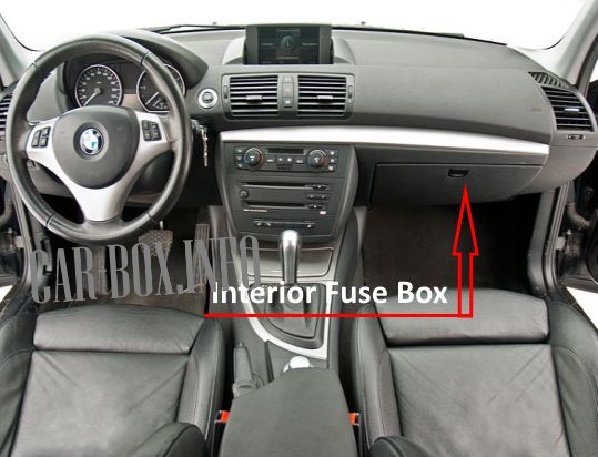
The distribution box is located on the passenger side behind the glove compartment. To access it, unlock the catches and tilt the glove compartment downwards.
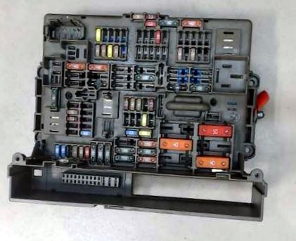
General view of the BMW 1 E81 / E87 interior fuse box.

Access example.
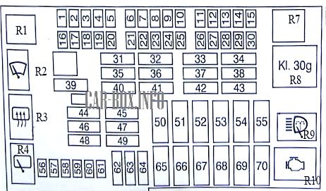
| Diagram | ||
|---|---|---|
|
||
| No. | Decryption | A |
| 1 | Empty | - |
| 2 | Rearview mirror with automatic dimming | 5 |
| 3 | Empty | - |
| 4 | Multifunctional control module 3 | 5 |
| 5 | Multifunctional control module 4 | 7.5 |
| 6 | Not used (^08/05) | |
| 7 | Empty | - |
| 8 | Audio equipment CD changer | 5 |
| 9 | Empty | - |
| 10 | Empty | - |
| 11 | Empty | - |
| 12 | Multipurpose module | 20 |
| 13 | i-drive control module | 5 |
| 14 | Empty | - |
| 15 | Empty | - |
| 16 | Horn (beep) | 15 |
| 17 | Navigation system | 5 |
| 18 | Audio system CD changer (^ 11/04) | 5 |
| 19 | Alarm system, keyless entry | 7.5 |
| 20 | Dynamic Stability Control | 5 |
| 21 | Door control module - driver's side, passenger side electric rear view mirror | 7.5 |
| 22 | Empty | - |
| 23 | Navigation system, TV tuner | 10 |
| 24 | Empty | - |
| 25 | Empty | - |
| 26 | Telematics | 10 |
| 27 | Door control module - driver's side, telephone | 5 |
| 28 | Multifunctional control module 4, parking control module | 5 |
| 29 | Heated front seats | 5 |
| 30 | Charging socket, BMW 1 E81/E87 cigarette lighter fuse | 20 |
| 31 | Dynamic stability control (^ 08/05) | 30 |
| 32 | Power seats, heated front seats | 30 |
| 33 | Power seat - passenger | 30 |
| 34 | Audio Device Amplifier | 30 |
| 35 | Fuel pump fuse (FP) H08/05 | 20 |
| 36 | Multifunctional control module 2 | 30 |
| 37 | Empty | - |
| 38 | Not used (^08/05) | |
| 39 | Wiper motor motor | 30 |
| 40 | Audio system (^ 08/05) | 20 |
| 41 | Multifunctional control module 2 | 30 |
| 42 | electric drive | 30 |
| 43 | Headlight washers | 30 |
| 44 | trailer control module | 30 |
| 45 | Trailer socket (^ 08/05) | 20 |
| 46 | Rear window heating | 4 |
| 47 | Not used (^08/05) | |
| 48 | Rear window washer/wiper system | 20 |
| 49 | Front passenger seat heater | 30 |
| 50 | Empty | |
| 51 | Multifunction control module 3 | 5 |
| 52 | Multifunctional control module 2 | 50 |
| 53 | Multifunctional control module 2 | 50 |
| 54 | Engine management | 60 |
| 55 | Empty | |
| 56 | central locking system | 15 |
| 57 | 15 | |
| 58 | Datalink connector (DLC), instrument cluster control module | 7.5 |
| 59 | Steering column function control module | 5 |
| 60 | Air conditioning (AC) | 7.5 |
| 61 | Luggage, glove box lamp, multifunction display | 10 |
| 62 | Rear power windows | 30 |
| 63 | Multifunctional control module | 30 |
| 64 | Rear power windows | 30 |
| 65 | Dynamic Stability Management | 40 |
| 66 | Fuel Filter Heater - Diesel | 50 |
| 67 | Heater / air conditioner (AC) | 50 |
| 68 | Empty | |
| 69 | Engine Coolant Fan Motor | 50 |
| 70 | Secondary air injection (AIR), if equipped | 50 |
| R1 | Windshield wiper motor motor 2 (included in fuse box / relay plate) | |
| R2 | Wiper motor motor 1 | |
| R3 | Rear window relay | |
| R4 | Rear window wiper relay | |
| R5 | Fuel pump relay (FP) (in fuse/relay housing) - if installed | |
| R6 | Circuit disconnect relay 2 (in fuse/relay housing) - if fitted | |
| R7 | Main ignition switch relay (in fuse/relay housing) | |
| R8 | Circuit disconnect relay 1 | |
| R9 | Headlight washer pump relay | |
| R10 | Secondary air pump relay (AIR) | |
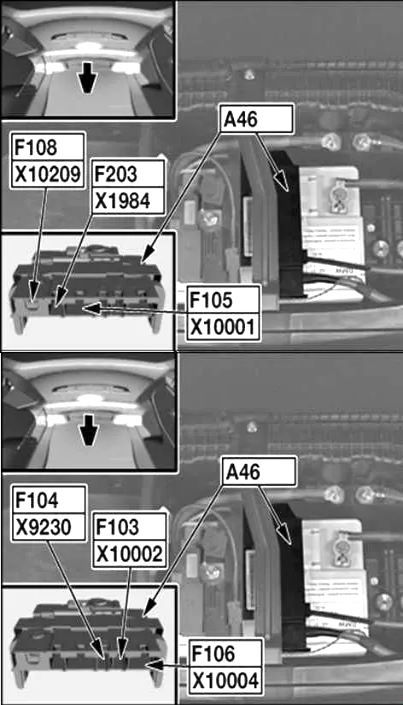
In the trunk
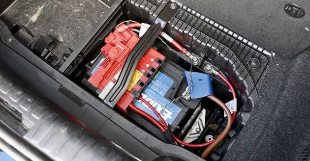
Located behind the floor pan, near the battery.
| Diagram | ||
|---|---|---|
|
||
| No. | Description | A |
| F103 | Reserve | — |
| F104 | Low battery sensor | — |
| F105 | Electronic Power Steering (EPS) | 100 |
| F106 | Additional electric heater | 100 |
| F108 | Junction box | 250 |
| F203 | Output for external battery connection - Main relay of the DDE system | 100 |
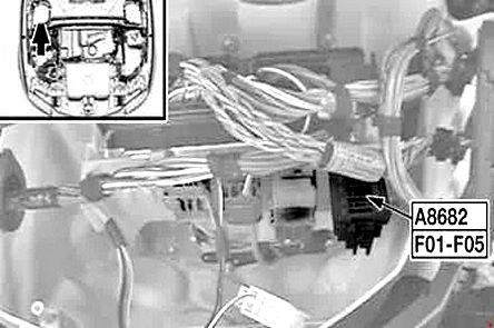
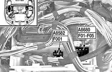
In the engine compartment
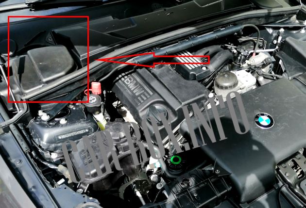
Located behind the cladding on the left side. The version depends on the engine type.
| Diagrams | ||
|---|---|---|
| No. | Description | A |
| Type M47/TU2 (118d, 120d) | ||
|
||
| F01 | Boost pressure regulator | 20 |
| Camshaft Hall Sensor | ||
| Rail line pressure control valve | ||
| F02 | Exhaust gas recirculation solenoid valve | 20 |
| Engine crankcase ventilation system heating | ||
| Switching e/valve of swirl valves | ||
| The Lambda probe | ||
| preheating control unit | ||
| Oil level sensor | ||
| F03 | Potential distributor B+ - Diesel engine digital electronic control system ECU | 30 |
| F04 | Electronics box fan | 10 |
| F05 | empty | — |
| Type N45 (116i) | ||

|
||
| F01 | Thermal anemometer air flow meter | 30 |
| Fuel tank vent valve | ||
| Oil level sensor | ||
| Suction jet pump intake valve | ||
| F02 | The Lambda probe | 30 |
| F03 | fuel injectors | 20 |
| crankshaft sensor | ||
| Camshaft position sensor | ||
| Electronics box fan | ||
| Junction box (fuel pump relay) | ||
| F04 | VANOS solenoid valve | 30 |
| DME control unit | ||
| F05 | Unload relay of contact 15 | 30 |
| Type N46 (118i, 120i) | ||
|
||
| F01 | fuel injectors | 20 |
| F02 | VANOS solenoid valve | 20 |
| Camshaft position sensor | ||
| Programmable cooling system thermostat | ||
| F03 | DME control unit | 30 |
| Thermal anemometer air flow meter | ||
| Oil level sensor | ||
| crankshaft sensor | ||
| Fuel tank vent valve | ||
| Engine crankcase ventilation system heating | ||
| F04 | Electronics box fan | 10 |
| Junction box | ||
| F05 | The Lambda probe | 30 |
| F001 | Unload relay of contact 15 | 10 |
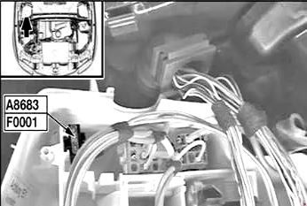
|
||
| F0001 | Valve actuator relay with infinitely variable stroke control | 40 |
| Type N52 (125i, 130i) | ||
|
||
| F01 | Ignition coils | 30 |
| Ignition coil interference suppression capacitor | ||
| F02 | Programmable Cooling System Thermostat | 30 |
| Electric coolant pump | ||
| Intake camshaft position sensor | ||
| Solenoid valve VANOS | ||
| Intake camshaft position sensor | ||
| F03 | crankshaft sensor | 20 |
| DME control unit | ||
| Fuel tank vent valve | ||
| Air mass meter | ||
| Oil condition sensor | ||
| crankshaft sensor | ||
| F04 | Engine crankcase ventilation system heating | 30 |
| The Lambda probe | ||
| F05 | Injector relay | 30 |
| F06 | EAC sensor | 10 |
| Electronics box fan | ||
| Muffler flap | ||
| Fuel Tank Leak Diagnostic Module | ||
| Junction box (K6304) | ||
| Thermoanemometric supplementary air flow meter | ||
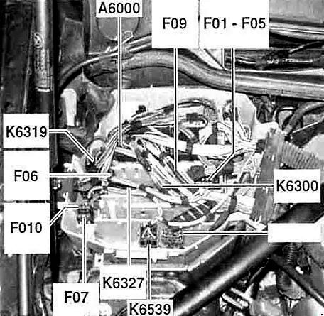
| F07 | Relay Valvetronic (WT) | 40 |
| F09 | Electric coolant pump | 30 |
| F010 | Crankcase ventilation heating relay | 5 |
| Ignition coils | ||
| A6000 | DME control unit | |
| A6300 | DDE system main relay | |
| A6319 | Relay Valvetronic (VVT) | |
| A6327 | Injector relay | |
| A6539 | Crankcase ventilation heating relay | |
| Type N54 (135i) | ||
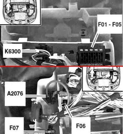
|
||
| F01 | Ignition coils | 30 |
| Ignition coil interference suppression capacitor | ||
| F02 | DME control unit | 30 |
| Electric coolant pump | ||
| Programmable thermostat | ||
| Intake camshaft position sensor | ||
| Solenoid valve VANOS | ||
| Exhaust camshaft position sensor | ||
| Wastegate valve | ||
| F03 | crankshaft sensor | 20 |
| Fuel tank vent valve | ||
| Oil condition sensor | ||
| quantity control valve | ||
| F04 | Crankcase ventilation system heating | 30 |
| The Lambda probe | ||
| F05 | empty | — |
| F06 | Electronics box fan | 10 |
| Muffler flap | ||
| USA: Fuel Tank Leak Diagnostic Module | ||
| F07 | Electric coolant pump | 40 |
| K6300 | DDE system main relay | - |
| A2076 | B+ power | - |
