E38 is the third generation of premium cars of the 7-series, produced from 1994 to 2001 by the German automaker BMW. Together with gasoline engines, for the first time in the history of the company on the premium class cars began to install diesel engines. In this article, we will take a detailed look at the fuse box diagrams for the BMW E38 (7 series; 3rd generation; 725tds, 728i, 730d, 730i, 735i, 740d, 740i, 750i) 1994, 1995, 1996, 1997. 1998, 1999, 2000, 2001 years of manufacture.

Here you will find the locations and photos of distribution boxes. Also, we will separately mark the fuse responsible for the cigarette lighter.
In the luggage compartment
The distribution box is located in the right side of the trunk above the battery under the trim.
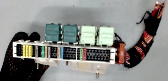
General view.
| Diagram | ||
|---|---|---|
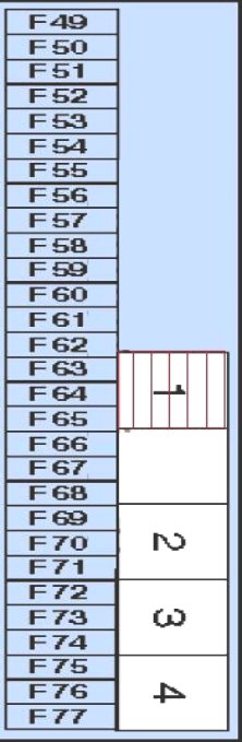
| Models up to 1997 | ||
|
||
| No. | Description | Current, A |
| F49 | Independent ventilation system | 15 |
| F50 | Independent heater | 15 |
| F51 | Sunroof | 20 |
| F52 | cigarette lighter fuse | 30 |
| F53 | Power rear seat | 20 |
| F54 | — | |
| F55 | Windshield wipers, power steering | 7.5 |
| F56 | Anti-theft system | 15 |
| F57 | Fuel module (fuel pump fuse) | 15 |
| F58 | Anti-theft system, central locking | 5 |
| F59 | Rear window heater | 30 |
| F60 | — | |
| F61 | A/C Fan Motor - Rear | 20 |
| F62 | Interior rearview mirror | 5 |
| F63 | Rear seat heater | 15 |
| F64 | parking system | 5 |
| F65 | Suspension control system | 15 |
| F66 | cigarette lighter | 5 |
| F67 | — | |
| F68 | A/C Fan Motor - Rear | 5 |
| F69 | Navigation system, audio system | 30 |
| F70 | Phone | 10 |
| 1 | Independent heater relay | |
| 2 | Main Ignition Relay | |
| 3 | Fuel pump relay | |
| 4 | Rear window heater relay | |
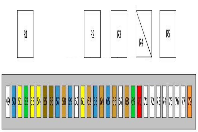
| After 1997 | ||
|
||
| No. | Decryption | Amps |
| 49 | Not | |
| 50 | Auxiliary heating system | 15 |
| Parking distance control system | ||
| 51 | Sunroof control unit | 20 |
| 52 | Cigarette lighter front and rear | 30 |
| 53 | Rear seat adjustment | 20 |
| 54 | trailer connector | 20 |
| 55 | General electrical control box | 7.5 |
| 56 | Security alarm | 7.5 |
| 57 | Fuel pump relay | 15 |
| 58 | Rear door lock switch | 5 |
| Vehicle tilt sensor | ||
| Electrochromic rearview mirror | ||
| Protection and switching unit | ||
| 59 | Refrigerator | 15 |
| 60 | Not used | 5 |
| 61 | Rear fan | 20 |
| Rear Fan Relay | ||
| 62 | Electrochromic rearview mirror | 5 |
| 63 | Heated rear seat switch | 15 |
| 64 | Parking assistance control unit | 5 |
| 65 | Switching module | 15 |
| Electronic damping control (EDC) | ||
| 66 | cigarette lighter | 5 |
| 67 | Not used | |
| 68 | Rear fan | 5 |
| Rear Fan Relay | ||
| 69 | Rear information display | 30 |
| 70 | Voice control unit | 10 |
| Charging system | ||
| phone | ||
| 71 | Intercom (special equipment) | |
| 79 | Relay, rear demister | 40 |
| R1 | Auxiliary heating system | |
| R2 | Fuel flap relay | |
| R3 | Unloader relay, terminal 15 | |
| R4a | Fuel module relay (fuel pump) | |
| R4b | Fan relay | |
| R5 | relay demistor | |
In the passenger compartment
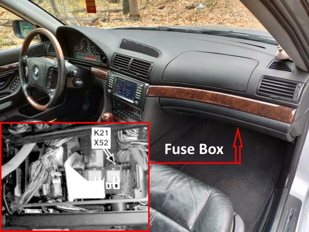
The distribution box is located behind the glove compartment.
| Diagram | |
|---|---|
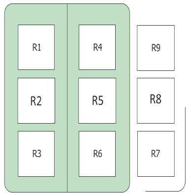
|
|
| No. | Decryption |
| R1 | headlight washer module |
| R2 | Air conditioning water valves |
| R3 | Trunk lid / tailgate control panel |
| R4 | shutdown |
| R5 | windshield heating |
| Heated nozzles | |
| R6 | fan |
| R7 | Additional cooling fan, speed 2 |
| R8 | Additional cooling fan, speed 1 |
| R9 | Additional cooling fan, speed 3 |
In the engine compartment
There are two distribution boxes here that are responsible for protecting the electrical circuits.
Fuse box
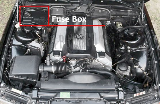
Located on the passenger side, closer to the windshield.
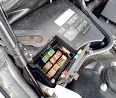
Access example.
| Diagram | ||
|---|---|---|
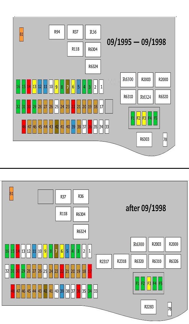
|
||
| No. | Decryption | Amps |
| 1 | — | |
| 2 | — | |
| 3 | windshield wiper | 30 |
| 4 | Windshield washers, headlight washer | 30 |
| 5 | Horn (beep) | 15 |
| 6 | Interior lamps, trunk lamp, windshield washers | 20 |
| 7 | Air conditioner | |
| 8 | Central locking, power door mirrors | 30 |
| 9 | AC condenser fan motor | 20 |
| 10 | Traction control | 25 |
| 11 | Air conditioner | 15 |
| 12 | Steering column position adjustment actuator | 15 |
| 13 | Steering column position adjustment actuator | |
| 14 | rear head restraint control unit | |
| (after 09.1998) Left lower A-pillar | ||
| Right lower front pillar | ||
| 15 | Power Seat (Driver's Side), Steering Column Adjuster | 30 |
| 16 | Power seat (passenger side) | 30 |
| 17 | ABS / ABS system, traction control, fuel module (fuel pump) | 10 |
| 18 | instrument cluster | 5 |
| 19 | — | 5 |
| 20 | Heater fan motor, air conditioner condenser fan motor, rear window heater, windshield heater | 5 |
| 21 | Garage door remote control system | 5 |
| 22 | Engine management | 10 |
| 23 | Lighting circuit control relay, instrument cluster | 5 |
| 24 | Engine management | 5 |
| 25 | — | |
| 26 | Immobilizer, automatic transmission selector lamp | 5 |
| 27 | Multifunction display | 5 |
| 28 | Windshield wipers, audio remote control system | 5 |
| 29 | Central locking system, power windows | 30 |
| 30 | Windshield washer nozzle heaters | 10 |
| 31 | Power door mirrors, central locking, power windows | 30 |
| 32 | Heater fan motor | 30 |
| 33 | ABS system | 25 |
| or | ||
| Air conditioning water valves | ||
| 34 | AC condenser fan motor | 40 |
| 35 | — | |
| 36 | Steering wheel heater | 10 |
| 37 | — | |
| 38 | AC condenser fan motor | 5 |
| 39 | seat heater | 15 |
| 40 | not used | 5 |
| or | ||
| diagnostic connector | ||
| 41 | Horn, instrument cluster, gear selector lamp | 5 |
| 42 | Charging socket, vanity mirror lamp | 7.5 |
| 43 | Safety Airbag | 5 |
| 44 | Immobilizer, lighting relay control, cruise control | 5 |
| 45 | Safety Airbag | 5 |
| 46 | On-board computer, audio system, telephone | 5 |
| 47 | Multifunction display, steering wheel adjustment mechanism | 5 |
| 48 | — | |
| 78 | Fan | 20 |
| 81 | Fan relay | 40 |
| F1 | Diagnostic connector | 30 |
| Engine control unit (DME) | ||
| DME relay | ||
| transmission control unit | ||
| F2 | Engine control unit (DME) | 20 |
| Engine Management (EML) | ||
| F3 | Oxygen sensor before catalytic converter | 20 |
| F4 | Engine control unit (DME) | 30 |
| Engine Management (EML) | ||
| transmission control unit | ||
| F5 | Ignition coils | 30 |
| R36 | Wiper Relay #1 | |
| R37 | Wiper Relay #2 | |
| R94 | Engine relay | |
| R118 | Air pump relay | |
| R2000 | Glow plug relay | |
| R2003 | Main relay DDE | |
| R6303 | Oxygen sensor relay | |
| R6304 | Secondary air injection pump relay | |
| R6310 | DME | |
| R6320 | ||
| R6324 | starter | |
| R2283 | preheating | |
| R2317 | DDE | |
| R2318 | ||
| R6300 | Relay DDE | |
| R6326 | Unloader relay, terminal 15 | |
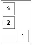
Additional relay block
Located on the left side.
| Diagram | |
|---|---|
|
|
| No. | Purpose |
| 1 | ABS pump |
| 2 | Exhaust air pump |
| 3 | air conditioning condenser fan (fusible link) |

Very good