E65 / E66 is the factory index of the fourth generation of BMW's 7 Series, produced from 2001 to 2008. In seven years, about 330,000 cars were produced. In this article, we will take a detailed look at the fuse box diagrams for the BMW E65 / E66 (7 series; 4th generation; 730d, 730i, 735i, 740d, 740i, 745d, 750i, 760LH, 760i) 2001, 2002, 2003, 2004, 2005, 2006, 2007, 2008 years of manufacture.

Here you will find the locations and photos of distribution boxes. The fuses responsible for the “Cigarette lighter” and “Fuel Pump” are highlighted in bold.
In the trunk
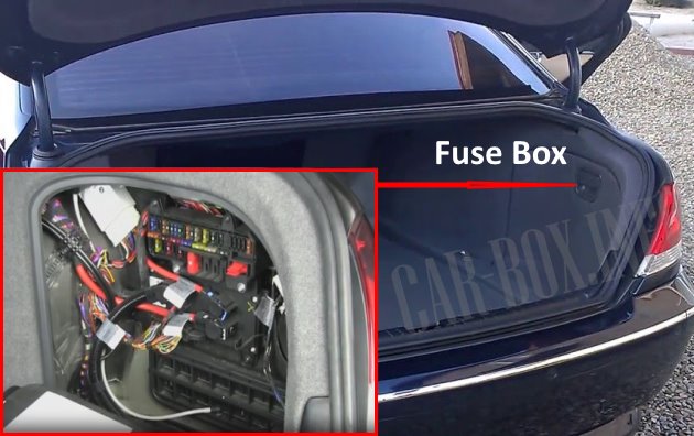
The distribution box is located on the right side behind the trim, you need to remove the panel to access it.
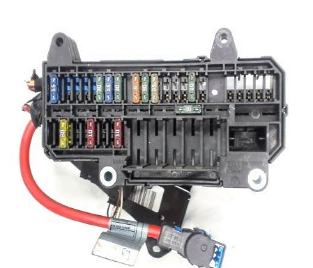
General view of the BMW E65 / E66 trunk fuse box.
| Diagram | ||
|---|---|---|

|
||
| No. | Decryption | A |
| F51 | Windshield heater relay | 15 |
| F52 | Refrigerator | 15 |
| F53 | Reserve | 5 |
| F54 | Control module of the central locking and engine starting remote control system | 5 |
| F55 | Rear seat heating control module | 30 |
| F56 | Power front seats | 30 |
| F57 | Reserve | 15 |
| F58 | Right front door electrical control module | 30 |
| F59 | Parking brake control module | 5 |
| F60 | Right rear door electrical control module | 30 |
| F61 | Parking brake control module | 30 |
| F62 | Active Suspension Compressor | 30 |
| F63 | Sunroof electric control unit | 20 |
| F64 | empty | - |
| F65 | Radio | 30 |
| F66 | Trailer electrical connector | 20 |
| F67 | empty | - |
| F68 | empty | - |
| F69 | empty | - |
| F70 | empty | - |
| F71 | empty | 5 |
| F72 | Suspension control unit | 7.5 |
| F73 | Fuel module (fuel pump fuse) | 15 |
| F74 | empty | - |
| F75 | Heated seats | 30 |
| F76 | Navigation system / DVD | 10 |
| F77 | Seat conditioning | 5 |
| F78 | Heated seats | 30 |
| F79 | Phone | 10 |
| F80 | empty | - |
| F81 | Trunk lid opening/closing actuator control unit | 50 |
| F82 | empty | - |
| F83 | Reserve | 40 |
| F84 | empty | - |
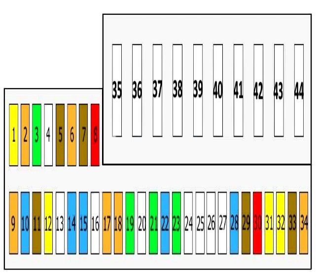
In the cabin

The distribution box is located behind the glove compartment.
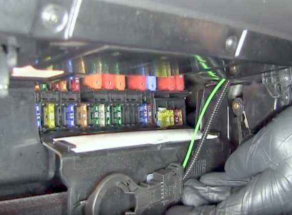
Access example.
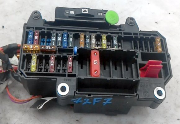
General view.
| Diagram | ||
|---|---|---|
|
||
| No. | Decryption | Amps |
| F1 | Additional heater | 20 |
| F2 | Antenna Motor | 5 |
| F3 | Body control unit | 30 |
| F4 | — | |
| F5 | center console | 7.5 |
| Information display | 7.5 | |
| Rear information display | 7.5 | |
| phone | 7.5 | |
| F6 | CD changer | |
| F7 | Speed control system | 7.5 |
| F8 | dynamic drive | 10 |
| F9 | Tire pressure monitoring system | 5 |
| F10 | Air conditioning electronic control unit | 15 |
| F11 | Rear information display | 7.5 |
| F12 | Steering column electrical control unit | 20 |
| F13 | empty | - |
| F14 | suspension system | 15 |
| F15 | Security and gateway module | 15 |
| driver's seat | 15 | |
| passenger seat | 15 | |
| F16 | empty | - |
| F17 | Dynamic Stability Control (DSC) | 5 |
| Light switch module | 5 | |
| F18 | Headlight correction control unit | |
| F19 | Left rear door electrical control unit | 30 |
| F20 | Dynamic Stability Control (DSC) | 25 |
| F21 | Left front door electrical control unit | 30 |
| F22 | transmission control unit | 15 |
| F23 | Power front seats | 30 |
| F24 | Night vision control unit | 10 |
| F25 | empty | — |
| F26 | empty | — |
| F27 | empty | — |
| F28 | Instrument cluster control unit | 15 |
| F29 | Diagnostic connector (DLC) | 7.5 |
| F30 | Electronics box (E-box) cooling fan / Starter relay / Fuel heater relay / Energy saving relay | 10 |
| F31 | cigarette lighter fuse | 20 |
| F32 | Charging connector(s) | 20 |
| F33 | Instrument panel | 7.5 |
| F34 | Audio amplifier | 5 |
| F35 | windshield wiper | 40 |
| F36 | Light module | 50 |
| F37 | Air conditioner/heater fan motor control unit | 40 |
| F38 | — | |
| F39 | ABS / ABS system | 50 |
| F40 | Integrated control unit | 60 |
| F41 | Fuel Heater Relay (Diesel) | 50 |
| F42 | Ignition lock control unit | 50 |
| F43 | BMW e65 cigarette lighter | 50 |
| F44 | Light module | 50 |
In the underhood space
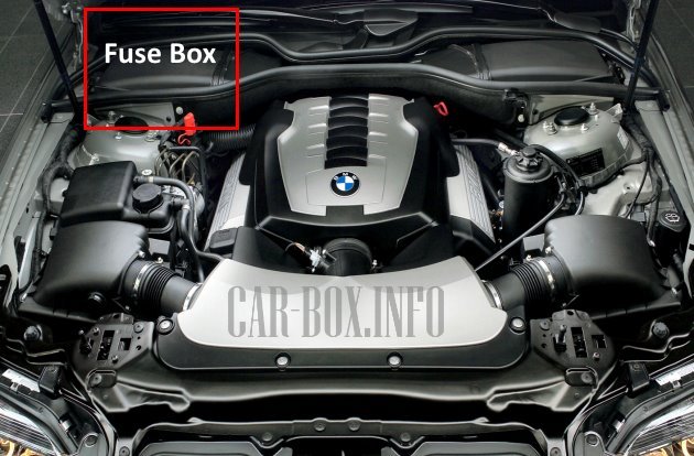
The distribution box is located on the right side behind the plastic cover. It has several variations depending on the equipment.
| Diagram | ||
|---|---|---|
| Type 1 | ||

|
||
| No. | Decryption | Amps |
| 1 | Ignition coils 1 - 3 | 30 |
| Ignition coils 4 - 6 | ||
| 2 | camshaft valve | 30 |
| DME | ||
| Idle speed drive | ||
| Fuel tank wiring harness | ||
| variable valve timing | ||
| 3 | Mass flow meter | 20 |
| crankshaft position sensor | ||
| Camshaft sensor | ||
| MAP-controlled engine cooling thermostat | ||
| 4 | Oxygen sensor on catalytic converter | 30 |
| Sequential gearbox | ||
| 5 | Injector relay | 30 |
| R1 | Injector relay | |
| R2 | DME relay | |
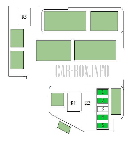
| Type 2 | ||
|
||
| No. | Purpose | A |
| 1 | Battery, B+ | 30 |
| DDE control unit | ||
| 2 | Canister purge valve | 30 |
| Boost pressure regulator valve | ||
| Heating unit | ||
| Intake manifold changeover valve | ||
| Mass flow meter | ||
| Rail pressure control valve | ||
| Hall Sensor | ||
| Speed sensor | ||
| 3 | Empty | - |
| 4 | EGR valve | 30 |
| Boost pressure regulator valve | ||
| Oil level sensor | ||
| Mass flow meter | ||
| 5 | DDE control unit | 30 |
| R1 | Main relay DDE | |
| R2 | Main relay DDE | |
| R3 | Starter relay | |
| Type 3 | ||

|
||
| No. | Purpose | A |
| 1 | Variable valve timing | 30 |
| DME | ||
| Injectors (cylinders 5 - 8) | ||
| 2 | Fuel tank cover | 20 |
| camshaft valve | ||
| Camshaft sensor | ||
| 3 | Ignition coils 1 - 4 | 20 |
| 4 | Ignition coils 5 - 8 | 20 |
| 5 | camshaft valve | 30 |
| Camshaft sensor | ||
| MAP-controlled engine cooling thermostat | ||
| crankshaft position sensor | ||
| Mass flow meter | ||
| 6 | injectors (cylinders 1 - 4) | 20 |
| 7 | transmission control unit | 20 |
| 8 | Oxygen sensors before and after the catalytic converter | 30 |
| Oil quality sensor | ||
| 9 | Fuel Tank Leak Diagnosis | 10 |
| Secondary air pump relay | ||
| Mass flow meter | ||
| Electronics box (E-box) cooling fan | ||
| exhaust manifold cover | ||
| Energy saving relay | ||
| 10 | Variable valve timing | 40 |
| 11 | 40 | |
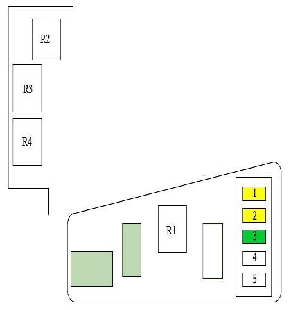
| Type 4 | ||
|
||
| No. | Description | A |
| 1 | Canister Purge Valves | 20 |
| Mass flow meter | ||
| Rail pressure control valve | ||
| Hall Sensor | ||
| 2 | crankcase heater | 20 |
| Swirl control valve, solenoid | ||
| Intake manifold changeover valve | ||
| Oil level sensor | ||
| Heating unit | ||
| 3 | Battery 30A, B+ | 30 |
| DDE control unit | ||
| 4 | Not used | |
| 5 | Not used | |
| R1 | DDE main relay | |
| R2 | Starter relay | |
| R3 | Not used | |
| R4 | Not used | |
