The E70 is the second generation of the German crossover X5. The car was presented in August 2006 at the Paris Motor Show. In 2010, the model was restyled. In this article, we will take a detailed look at the fuse diagrams for the the BMW X5 ( 3.0d, 4.8i, xDrive 30d, xDrive 35d, xDrive 40d, xDrive 50i, xDrive M50d) of the 2nd generation in the e70 body: 2006, 2007, 2008, 2009, 2010. 2011, 2012, 2013 release.

Here you will find the locations and photos of distribution boxes. The fuses responsible for the “Cigarette lighter” and “Fuel Pump” are highlighted in bold.
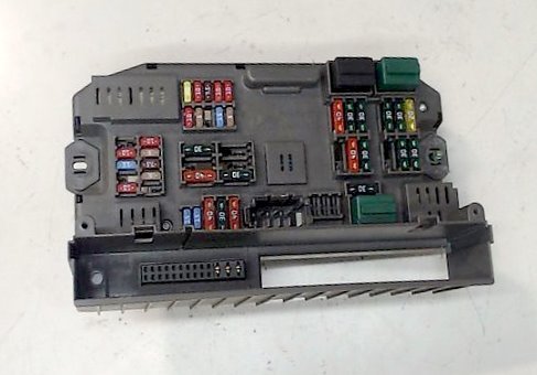
In the luggage compartment
Fuse box
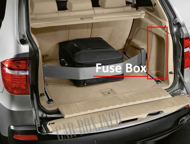
The main distribution box is located under the casing on the right side.
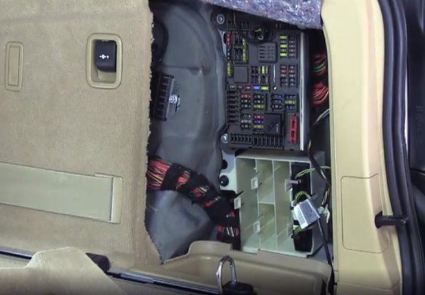
Access example.
| Diagram | |||
|---|---|---|---|
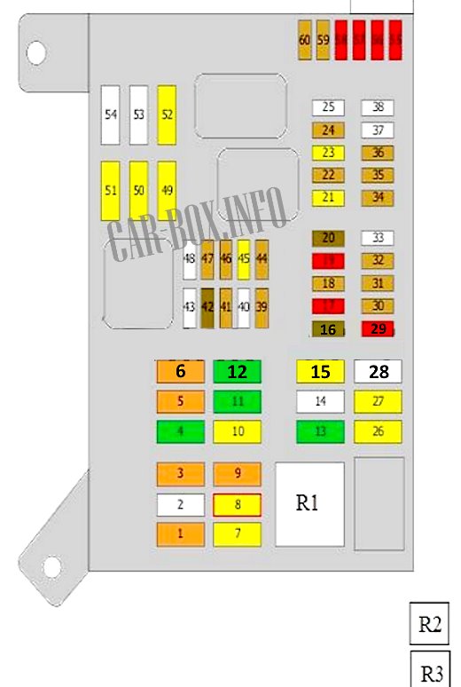
|
|||
| No. | Decryption | A | |
| 1 | additional heater | 30/40 | |
| 2 | transfer case control unit | 25 | |
| 3 | Additional heater | 40 | |
| 4 | Parking brake control unit | 30 | |
| 5 | Additional heater | 30/40 | |
| 6 | Footwell control unit | 40 | |
| 7 | Fuel pump relay | 20 | |
| Auxiliary relay, fuel pump | |||
| 8 | Rear fan motor | 15/20 | |
| 9 | rear door opening/closing drive control unit | 40 | |
| 10 | Rear left heated seat | 20 | |
| Terminal 15 supply voltage relay | |||
| 11 | seat control unit | 30 | |
| Driver seat adjustment switch | |||
| Lumbar support, solenoid | |||
| 12 | seat control unit | 30 | |
| Passenger seat adjustment switch | |||
| Lumbar support, solenoid | |||
| 13 | Audio output amplifier | 30 | |
| 15 | Fuel module control (fuel pump) | 30 | |
| 16 | Speakers | 7.5 | |
| 17 | ride height control | 10 | |
| Rear information display | |||
| 18 | Rear View Camera | 5 | |
| Rear car entertainment | |||
| Rear socket 12V | |||
| 19 | Navigation system receiver | 10 | |
| 20 | USB | 7.5 | |
| TCU | 20 | ||
| 21 | Cigarette lighter fuse (front) | ||
| 22 | heated seats | 5 | |
| Terminal 15 supply voltage relay | |||
| 23 | Cigarette lighter fuse (center armrest) | 20 | |
| 24 | Parking assist, sunroof | 5 | |
| 25 | Empty | ||
| 26 | Trailer electrical connector | 20 | |
| 27 | Sunroof | 20 | |
| 28 | Spare | 20 | |
| 29 | multimedia control unit | 5 | |
| 30 | active suspension | 5 | |
| 31 | drive for opening / closing the rear door (trunk) | 5 | |
| 32 | Fuel Tank Leak Diagnosis | 5 | |
| 33 | Empty | ||
| 34 | Dashboard Fuse/Relay Box | 5 | |
| 35 | Transfer box control unit | 5 | |
| 36 | air conditioner | 5 | |
| 39 | Parking brake control unit | 5 | |
| Antenna selection control unit | |||
| 41 | Instrument panel, diagnostic connector | 5 | |
| 42 | Access control unit | 7.5 | |
| Door control unit | |||
| 43 | Empty | ||
| 44 | steering column electrical equipment | 5 | |
| 45 | rear door opening/closing drive | 20 | |
| 46 | TCU | 5 | |
| 47 | Navigation system | 5 | |
| 48 | Empty | ||
| 49 | Heated rear seat control unit | 20 | |
| 50 | heated left front seat | 20 | |
| 51 | heated right front seat | 20 | |
| 52 | multimedia control unit | 20 | |
| 53 | Trailer control unit | 25 | |
| 54 | 5 | ||
| 55 | Secondary Door Closing Motor (Front Right) | 10 | |
| 56 | Secondary Door Closing Motor (Front Left) | 10 | |
| 57 | Secondary Door Closing Motor (Rear Left) | 10 | |
| 58 | Auxiliary door closing motor (rear right) | 10 | |
| 59 | seat switch (front left) | 5 | |
| 60 | seat switch (front right) | 5 | |
| R1 | Circuit disconnect relay | ||
| R2 | Fuel module relay (fuel pump) | ||
| R3 | Terminal 15 supply voltage relay | ||
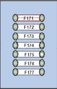
Power fuses
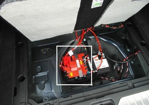
On the positive terminal of the battery (located in a niche under the floor) there is a board consisting of high-power fuse-links.
| Diagram | ||
|---|---|---|
|
||
| No. | Decryption | A |
| F171 |
|
100 |
| F172 | Fuses in the main luggage compartment | 100 |
| or | ||
| Additional heater | ||
| F173 | Cabin distribution box | 250 |
| F174 | empty | - |
| F175 | empty | - |
| F176 | Height Control Unit Relay Valve Lift | 80 |
| or | ||
| Main relay DDE | ||
| F177 | empty | - |
In the passenger compartment
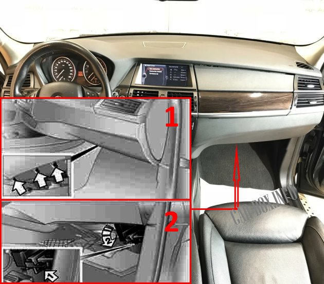
The distribution box is located at the feet of the passenger in front. To access it, it is necessary to unscrew the three fixing screws (1) and lower the cladding. Then (2) unscrew the screw 1 and lower the block holder 2 down .
General view.
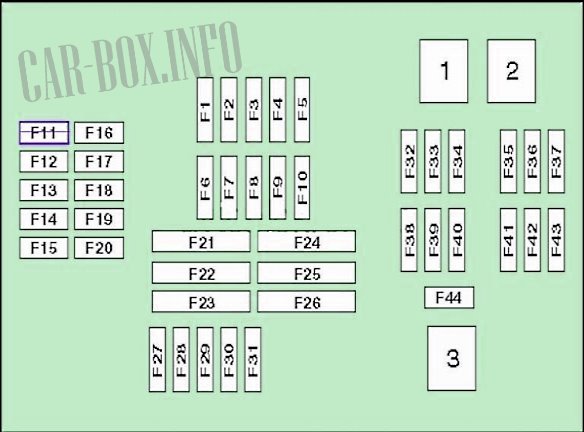
| BMW X5 E70 Cabin Fuse Diagram | ||
|---|---|---|
|
||
| No. | Decryption | A |
| 1 | Steering column adjustment | 20 |
| Conditioning control | ||
| 2 | Glove box lock drive, central locking | 10 |
| 3 | Charging system | 7.5 |
| Horn | ||
| Automatic air conditioner | ||
| Manual air conditioner | ||
| 4 | Electronic engine control unit | 10 |
| 5 | Sunroof | 10 |
| 6 | CD changer | 10 |
| DVD | ||
| 7 | Secondary air pump relay | 5 |
| Tire pressure control unit (RDC) | ||
| 8 | Speakers | 7.5 |
| 9 | Horn | 15 |
| 10 | Hand brake | 5 |
| central locking | ||
| 11 | Auxiliary heating system | 20 |
| 12 | Steering column electrical control unit | 10 |
| 13 | Electronic gearbox control unit | 15 |
| 14 | dynamic drive | 10 |
| 15 | Gearbox selector | 10 |
| 16 | Power window switch | 7.5 |
| 17 | video system | 7.5 |
| Multifunction display | ||
| Conditioning control | ||
| 18 | Head-Up Display Control Unit | 7.5 |
| Electronics box (E-box) cooling fan | ||
| 19 | Air conditioning | 5 |
| Dynamic Stability Control (DSC) | ||
| Sunroof | ||
| 20 | Empty | |
| 21 | Rear window heater | 30 |
| 22 | Empty | |
| 23 | Footwell control unit | 40 |
| 24 | power steering | 40 |
| 25 | Spare | 30 |
| 26 | headlight washer pump | 30 |
| 27 | central locking | 15 |
| 28 | 15 | |
| 29 | Power windows rear | 40 |
| 30 | central locking | 30 |
| 31 | Power windows rear | 40 |
| 32 | Active Suspension Compressor | 40 |
| 33 | Footwell control unit | 30 |
| 34 | 30 | |
| 35 | crankshaft position sensor | 30 |
| Hot Film Air Mass Sensor | ||
| Intake camshaft position sensor | ||
| Exhaust camshaft valve | ||
| Oil temperature sensor | ||
| MAP-controlled engine cooling thermostat | ||
| Camshaft adjustment valve | ||
| 36 | Injectors (cylinders 1 - 4) | 30 |
| Fuel tank vent solenoid valve | ||
| Intake camshaft position sensor | ||
| Exhaust camshaft position sensor | ||
| Camshaft adjustment valve | ||
| 37 | Rear wiper motor | 30 |
| 38 | Terminal 15 supply voltage relay | 30 |
| 39 | central locking | 40 |
| 40 | ABS electronic control unit | 30 |
| 41 | Hot Film Air Mass Sensor | 7.5 |
| 42 | DME | 30 |
| Valve timing adjustment unit | ||
| Injectors (cylinders 5 - 8) | ||
| 43 | Oxygen sensors behind and before the catalytic converter | 30 |
| 44 | Windshield wiper motor | 30 |
| R1 | Active Suspension Compressor Relay | |
| R2 | Rear window wiper relay | |
| R3 | Windshield wiper motor relay | |
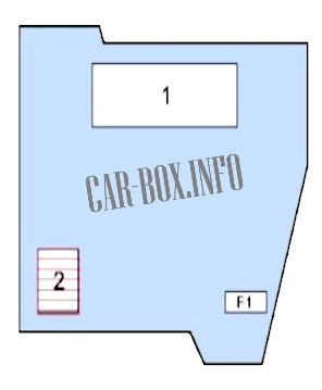
In the engine compartment

The distribution box is located on the right side, it is closed with a protective cover.
| Diagram | |
|---|---|
|
|
| No. | Description |
| 1 | ECU engine |
| 2 | Valve Height Control Relay |
| F1 | Valve Height Control Relay 40 A |
General arrangement
Location of the electronic components.

|
|
| No. | Component |
| 1 | ABS electronic module |
| 2 | Air purity sensor (air conditioning system) - Engine compartment, right side |
| 3 | A/C/heater fan motor control module, front - behind the air conditioning/heater control panel |
| 4 | A/C/Heater Fan Motor Control Module, Rear - Center Console |
| 5 | Power steering control module - behind the wheel arch, left |
| 6 | Active suspension control module - right side of luggage compartment |
| 7 | Antenna Booster - Rear Door |
| 8 | Impact sensor (SRS) 1 - suspension (front left) |
| 9 | Impact sensor (SRS) 2 - suspension (front right) |
| 10 | Side impact sensor 1 - B-pillar top |
| 11 | Side impact sensor 2 - in the door |
| 12 | Side impact sensor 3 - upper part of the B-pillar |
| 13 | Side impact sensor 4 - in the door |
| 14 | Vehicle tilt sensor (anti-theft system) - in the anti-theft siren |
| 15 | Anti-theft siren - Engine compartment, left side |
| 16 | Audio Output Amplifier - LH Trunk |
| 17 | Additional heater, before, - the Left part of the bottom |
| 18 | Auxiliary heater, rear left - under the left seat |
| 19 | Auxiliary heater, rear right - under the right seat |
| 20 | Battery - left side of luggage compartment |
| 21 | Battery Status Sensor - On Battery |
| 22 | Battery Current Monitor Relay - Luggage Compartment RH |
| 23 | Diagnostic connector (DLC) |
| 24 | audio control unit (DAB) - left side of the luggage compartment |
| 25 | multifunction digital display control unit - luggage compartment left side |
| 26 | ECM - in the fuse/relay box in the engine compartment |
| 27 | Fuel pump control unit (3.0si) - right side of luggage compartment |
| 28 | Fuel pump relay (4,8i) - right side of luggage compartment |
| 29 | Underhood fuse and relay box |
| 30 | Passenger compartment fuse box |
| 31 | Fuse/Relay Box, Luggage Compartment 1 |
