The F15 is the third generation of the mid-size crossover X5 of the German company BMW. The release was launched in November 2013 in Europe. Simultaneously with the launch of the new model, the previous one, the E70, was discontinued. In this article, we will take a detailed look at the fuse diagrams for the the 3rd generation BMW X5 (f15): 2013, 2014, 2015, 2016, 2017, 2018 of release.

Here you will find the locations and photos of distribution boxes. The fuse responsible for the “Cigarette lighter” is highlighted in bold.
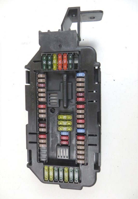
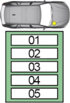
In the trunk

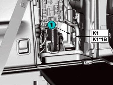
The distribution box is located behind the casing on the right side.

General view.
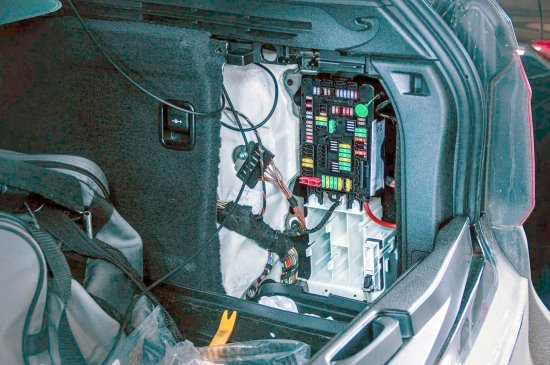
Access example.
| Assigment of fuses in the BMW X5 (F15) luggage compartment | ||
|---|---|---|
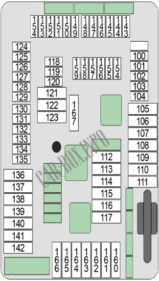
|
||
| No. | Decryption | A |
| 100 | Parking brake button | 5 |
| 101 | Right headlight | 15 |
| 102 | High voltage battery pack | 5 |
| 103 | Siren with security tilt sensor | 5 |
| 104 | Parking Brake Control Module, Natural Vacuum Leak Detection (NVLD) | 5 |
| 105 | Electric reversible seat belt retractor right | 30 |
| 106 | Torque distribution between the wheels of the rear axle | 30 |
| 107 |
|
40 |
| 108 | empty | - |
| 109 | empty | - |
| 110 | Air Suspension Compressor Relay | 40 |
| 111 | empty | - |
| 112 | Hybrid pressure tank electronics | 20 |
| 113 | Trailer electrical connection module | 30 |
| 114 | 30 | |
| 115 | Right headlight | 20 |
| 116 | Parking brake control unit | 30 |
| 117 | Electric reversible seat belt retractor, left | 30 |
| 118 | Video switcher (VSW) | 5 |
| 119 | empty | - |
| 120 | Power control unit | 5 |
| N20: Charging box for additional battery | 5 | |
| 121 | Head device | 20 |
| 122 | Audio amplifier | 30 |
| 123 | empty | - |
| 124 | Video module | 5 |
| 125 | empty | - |
| 126 | Rear Door Closer Drive (Passenger Side) | 10 |
| 127 | DVD changer | 5 |
| 128 | Wireless charging station, antenna booster (wireless charging), base board | 5 |
| 129 | Active Sound Design (ASD) audio system | 15 |
| 130 | Automatic tailgate lift | 5 |
| 131 | Luggage compartment lighting, trunk button on tailgate from inside, noise filter | 5 |
| 132 | Rear axle torque distribution, electronic ride height control | 5 |
| 133 | Rear climate control | 5 |
| 134 | Rear door closer drive (driver's side) | 5 |
| 135 | Gas generator emergency shutdown terminals | 5 |
| 136 | empty | - |
| 137 | empty | - |
| 138 | empty | - |
| 139 | Trailer socket | 20 |
| 140 | Trunk lid lock | 20 |
| 141 | empty | - |
| 142 | empty | - |
| 143 | refrigerator relay | 10 |
| 144 | Control unit for selective catalytic reduction (SCR - Selective Catalytic Reduction) | 15 |
| 145 | Parking aid, information system fan | 5 |
| 146 | Silencer electric damper (No. 1, No. 2) | 15 |
| 147 | Control unit for selective catalytic reduction (SCR - Selective Catalytic Reduction) | 15 |
| 148 | Lane Change Warning (SWW) | 5 |
| 149 | Right headlight | 7.5 |
| 150 | →06.2016: Contactless tailgate return electronic unit, comfort electronic charge (hybrid) | 5 |
| 07.2016→: Contactless tailgate return electronic unit, convenience electronic charge (hybrid), tailgate function module | 7.5 | |
| 151 | USB-HUB (USB connector #1/#2, AUX-In connector) | 5 |
| 152 | Electric reversible seat belt retractor left/right | 5 |
| 153 | Control unit for selective catalytic reduction (SCR - Selective Catalytic Reduction) | 15 |
| 154 | Surround Camera (TRSVC), Rear View Camera | 5 |
| 155 | Front passenger's door closer drive | 10 |
| 156 | Driver's door closer drive | 10 |
| 157 | empty | - |
| 158 | Audio system in the rear | 10 |
| 159 | Audio amplifier, information system fan | 5 |
| 160 | Rear heater | 20 |
| 161 | empty | - |
| 162 | Sockets in the second row of seats, socket in the luggage compartment | 20 |
| 163 | Trailer electrical connection module | 30 |
| 164 | Heated rear right seat | 30 |
| 165 | Fuel pump control unit (EKPS) | 20 |
| 166 | Heated rear left seat | 30 |
| 167 | Driver's door closer drive, front passenger's door closer drive | 30 |
|
||
| Relay for air suspension and refrigerator (if equipped). | ||
In the passenger compartment
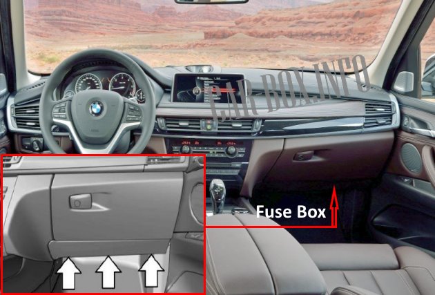
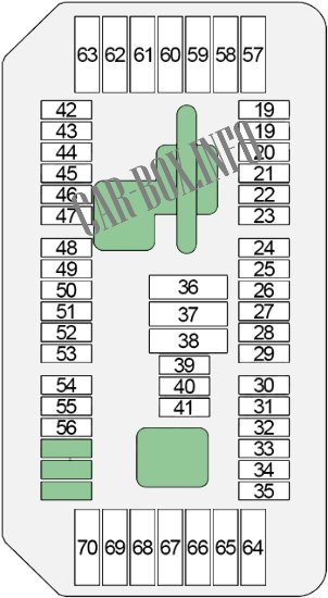
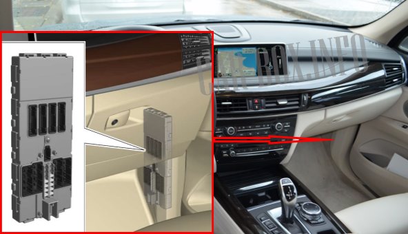
The main distribution box is located under the glove compartment in the front passenger footwell area. To access it, you need to unscrew the fasteners of the cover.
The photo shows an example.
| Diagram | ||
|---|---|---|
|
||
| No. | Decryption | Amps |
| 19 | remote control receiver | 5 |
| 20 | ceiling console | 5 |
| 21 | Preheating control unit | 5 |
| 22 | Driver's door switch box, passenger's side outside rearview mirror | 7.5 |
| 23 | Engine Management System (DME) | 10 |
| 24 | Electronic transmission control system | 10 |
| 25 | Touchbox, controller (joystick) | 5 |
| 26 | Retractable instrument panel speaker, heated rear left/right seat switch | 5 |
| 27 | Driver/Passenger Seat Lumbar Support Valve Block, Driver/Passenger Side Seat Adjustment Switch Block | 10 |
| 28 | Rain/light/sun sensor, overhead console, vanity mirror lights | 5 |
| 29 | Additional coolant pump | 15 |
| 30 | Charge Air Cooler Coolant Pump | 10 |
| 31 | Opening relay for electric fan | 5 |
| 32 | Transfer case | 5 |
| 33 | N63, S63: Turbocharger coolant pump | 5 |
| N20: Electric air conditioning compressor, electric auxiliary heater | 5 | |
| 34 | Integrated Chassis Management (ICM) | 5 |
| 35 | Electrochromic rear view mirror | 5 |
| 36 | Socket in the armrest | 20 |
| 37 | BMW x5 f15 cigarette lighter fuse | 20 |
| 38 | Ceiling console (terminal 30 supply) | 20 |
| 39 | Left headlight | 15 |
| 40 | - | - |
| 41 | S63: Coolant pump for charge air cooler | 10 |
| N20: Refrigerant shut-off valve in vehicle interior, electrical machine control (EME) | 10 | |
| 42 | Electronic damping control, electrochromic rear view mirror | 5 |
| 43 | Directional illumination left/right | 5 |
| 44 | Camera Based Driver Assistance Systems (KAFAS), Active Steering System | 7.5 |
| 45 | Active Cruise Control (ACC), Automatic Outside Air Contamination Control (AUC) sensors | 5 |
| 46 | Radiator shutter drive | 5 |
| B47, N47, N57: Heating of the engine ventilation system, radiator shutter drive | 5 | |
| 47 | Night Vision Electronics (NVE), Vehicle Sound Generator (VSG) | 5 |
| 48 | Switching center in the steering column | 10 |
| 49 | Steering angle sensor | 5 |
| N57D30T1: Coolant reservoir shut -off valve, steering wheel angle sensor | 5 | |
| fifty | instrument cluster | 5 |
| 51 | - | - |
| 52 | instrument cluster | 7.5 |
| 53 | Glove box lighting, instrument panel trim strip lighting (driver/passenger side), instrument panel trim strip lighting on driver's side, driver/passenger footwell lighting | 5 |
| 54 | Gear Select Switch (GWS) | 10 |
| 55 | Servotronic (SVT), electromechanical power steering (EPS) | 5 |
| 56 | Vertical Dynamics Management (VDM) | 5 |
| 57 | Left headlight | 20 |
| 58 | Dynamic Stability Control (DSC) | 30 |
| 59 | Active Steering System | 40 |
| 60 | heater | 40 |
| 61 | Electronic damping control system | 20 |
| 62 | →06.2016: Vertical Dynamics Management (VDM) | 30 |
| 07.2016→: Vertical Dynamics Management (VDM) | 20 | |
| 63 | Transfer box (VTG) | 30 |
| 64 | Front Passenger Seat Heating Module | 30 |
| 65 | Driver seat heating module | 30 |
| 66 | Autonomous/additional heater | 20 |
| 67 | Driver's Side Seat Adjustment Switch Block (Without Seat Module (SMFA)), Driver's Seat Module (SMFA) | 30 |
| 68 | Front Passenger Side Seat Adjustment Switch Block (Without Seat Module (SMBF)), Front Passenger Seat Module (SMBF) | 30 |
| 69 | Electronic transmission control system (EGS) | 20 |
| 70 | Electric steering column adjustment | 20 |
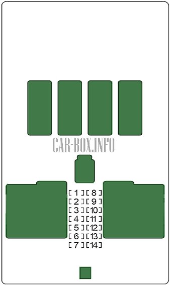
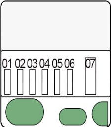
The additional block is located near the passenger's feet on the A-pillar and is covered with a sheathing.
| Diagram | ||
|---|---|---|
|
||
| No. | Purpose | A |
| 1 | Front passenger window drive | 30 |
| 2 | Rear power window drive, driver's side | 30 |
| 3 | Front passenger door lock | 20 |
| 4 | Driver's power window drive | 30 |
| 5 | Rear window heating | 30 |
| 6 | Passenger rear power window drive | 30 |
| 7 | Driver door lock | 20 |
| 8 | - | - |
| 9 | Switching center in the steering column, light switch unit, driver assistance system control unit with hazard warning light switch | 5 |
| 10 | Left headlight | 7.5 |
| 11 | Diagnostic socket, heating and air conditioning system, dynamic stability control (DSC) | 7.5 |
| 12 | Telematic communication unit, electronic units of door handles | 5 |
| 13 | Horn (high/low tone) | 15 |
| 14 | - | - |
In the engine compartment
The distribution box is located on the right side of the engine compartment.
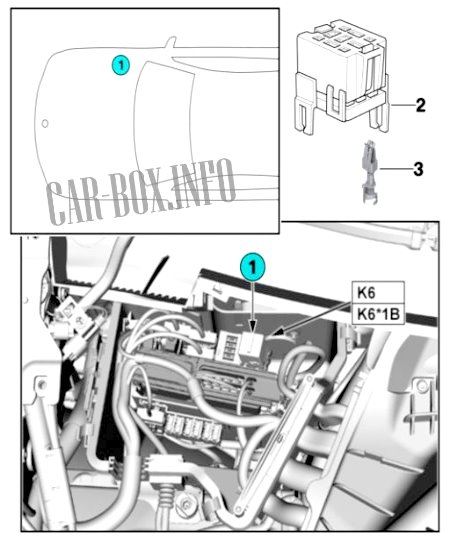
K6 - engine relay.
| The diagram of elements in the engine compartment | ||
|---|---|---|
| Main box | ||
|
||
| No. | Description | A |
| 1 | Camshaft Position Sensor, Quantity Control Valve, Rail Pressure Control Valve, Turbine Control Flap Pressure Converter, Low Pressure Compressor Bypass Valve Changeover Valve (Except USA), EGR Auxiliary Cooler Bypass Damper Changeover Valve (USA), Pressure Regulator boost pressure (performance class "T"), boost pressure regulator - high pressure stage (variable turbocharging geometry (performance class "S")), boost pressure regulator No. 2 - high pressure stage (variable turbocharging geometry (N57D30S1)) | 20 |
| 2 | Lambda probe upstream of catalytic converter, hot film air mass meter, engine mount stiffness control valve, lambda probe downstream of catalytic converter, oil condition sensor, EGR cooler bypass flap changeover valve, high pressure compressor sequence changeover valve #2, converter pressure relief valve | 20 |
| 3 | Diesel Engine Management System (DDE) | 30 |
| 4 | Nitrogen oxide sensor before SCR catalytic converter, coolant pump for EGR cooling (→04.2014), EGR low temperature cooling changeover valve, diesel particle sensor | 10 |
| 5 | Pressure converter for bypass valve, changeover valve for turbine control flap, coolant pump relay | 10 |
| Maintenance free block | ||
|
||
| No. | Decryption | A |
| 1 | Engine management system (DME) - ignition system | 25 |
| 2 | Engine management system (DME) - fuel injection system | 25 |
| 3 | 15 | |
| 4 | 20 | |
| 5 | Engine Management System (DME) - Valvetronic | 40 |
| 6 | 40 | |
| 7 | Empty | - |
| Relay | ||
| R1 | Unloader relay for ignition and fuel injection | |
| R2 | Relief relay for Valvetronic | |
| R3 | DME main relay | |
