
First-generation Ford Focus (European and North American models; chassis code C170) was produced from 1998 through 2005, receiving one mid-cycle facelift. Below, you will find fuse and relay box diagrams, location descriptions, and circuit assignments for the Mk1 Ford Focus. The fuse assigned to the "Cigarette lighter" is highlighted in bold.
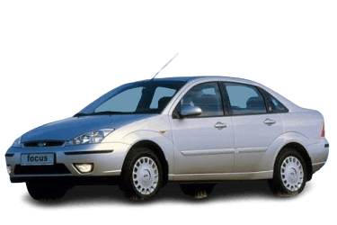
Fuse assignments and circuit protection ratings may vary depending on the model year and target market (European vs. North American specifications).
The Ford Focus Mk1 features two primary junction boxes: one inside the passenger compartment and another in the engine compartment.
In the passenger compartment
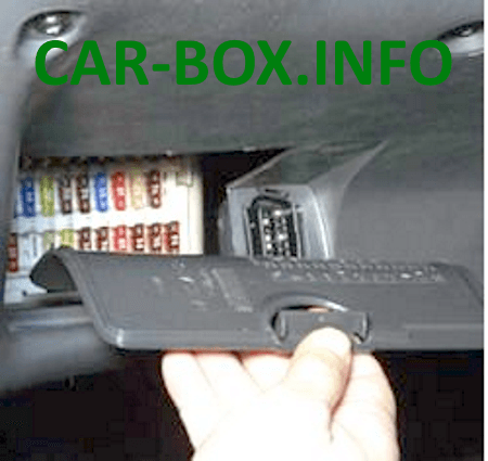
Located on the driver’s side of the dashboard, behind the glove box or lower access cover.
| Diagram | |
|---|---|
|
|
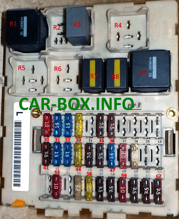
| No. | Fuse Description |
| 30 | 10A – Exterior lighting switch / 7.5A ABS control module |
| 31 | 15A – Audio system / Radio |
| 32 | 15A – Turn signals / 10A Exterior lighting switch |
| 33 | 20A – Horn, power seat adjustment, sunroof / 15A Anti-theft alarm system |
| 34 | 20A – Sunroof, horn |
| 35 | 7.5A – Interior lighting, power exterior mirrors |
| 36 | 7.5A – Electronic control modules, instrument cluster, A/C control module, alarm ('02–'04) |
| 37 | 25A – Power windows (left side) |
| 38 | 25A – Power windows (right side) |
| 39 | 15A – Power seat adjustment / 10A Reversing lights, automatic transmission control |
| 40 | 10A – Reversing lights / 25A Power windows, central locking |
| 41 | 7.5A – Audio system (auxiliary / memory) |
| 42 | 15A – Brake lights (stop lamps) |
| 43 | 15A – Power windows, rear window wiper |
| 44 | 20A – Front fog lights |
| 45 | 7.5A – Air conditioning system, air recirculation flap |
| 46 | 7.5A – ABS control module / 15A Cigarette lighter |
| 47 | 15A – Cigarette lighter / 7.5A Parking lights (left) |
| 48 | 10A – Data Link Connector (DLC / Diagnostic port) / 7.5A Parking lights (right) |
| 49 | 25A – Heated rear window (defroster) |
| 50 | 7.5A – Heated exterior mirrors, audio system, instrument cluster, central timer module |
| 51 | 7.5A – Heated exterior mirrors |
| 52 | 15A – Heated front seats |
| 53 | 10A – Reversing lights, heated windshield washer nozzles |
| 54 | 15A – Brake lights |
| 55 | 25A – Front power windows / 20A Windshield wipers |
| 56 | 20A – Windshield wipers / 25A Power side windows |
| 57 | 7.5A – Side marker / position lights (right) |
| 58 | 7.5A – Side marker / position lights (left) or air conditioning, blower motor |
| 59 | 10A – Exterior lighting switch, electronic control module, instrument cluster |
| 60 | 7.5A – Airbag control module (SRS) |
| 61 | 7.5A – Electronic control modules, instrument cluster |
| 62 |
|
| 63 | 20A Central locking |
| Depending on the model year, either Fuse 46 or Fuse 47 (15A) powers the cigarette lighter socket. | |
| R1 | Starter relay |
| R2 | Rear window wiper relay |
| R3 | Windshield wiper relay |
| R4 | Power socket (cigarette lighter) relay |
| R5 | Reserved / Spare |
| R6 | Reserved / Spare |
| R7 | Horn relay |
| R8 | Battery saver relay |
| R9 | Heated rear window / heated mirrors relay |
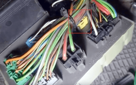
Please note: Fuse 63 is located on the back of the junction box module. |
|
In the engine compartment
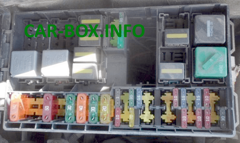
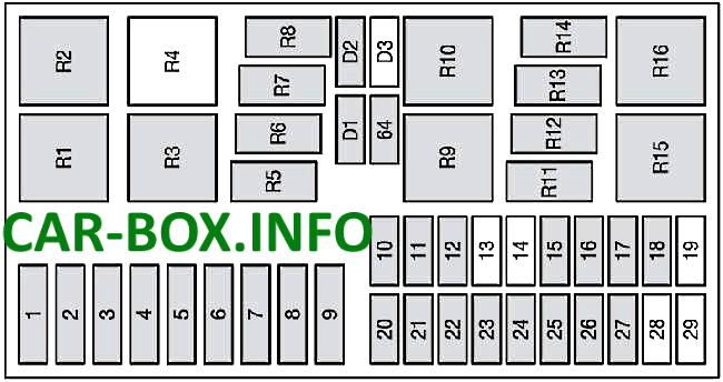
Located beneath the protective cover on the left side of the engine compartment.
| Diagram | |
|---|---|
|
|
| No. | Circuit / Component Protected |
| 1 | 40A – Main power supply circuit |
| 2 | 30A – Engine cooling fan (A/C system) |
| 3 | 30A – Engine cooling fan (2.0L) |
| 4 | 50A – Heated windshield |
| 5 | 60A – Diesel glow plugs |
| 6 | 30A / 50A – Radiator cooling fan (A/C system) |
| 7 | 40A – Main power supply to vehicle electrical system |
| 8 | 30A – Ignition switch, starter motor |
| 9 | 20A – Engine Control Module (ECM / PCM) |
| 10 | 10A – Battery charging monitor, Data Link Connector (DLC) |
| 11 | 30A – Anti-lock Braking System (ABS) |
| 12 | 15A – Fuel pump / high-pressure fuel pump (Diesel) |
| 13 | 30A – Headlight washer system |
| 14 | 10A – Daytime running lights (DRL) |
| 15 | 10A – A/C compressor clutch |
| 16 | 10A – Low beam headlight (left) |
| 17 | 10A – Low beam headlight (right) |
| 18 | 10A – Heated Oxygen Sensor (HO2S / Lambda probe) |
| 19 | 10A – Daytime running lights (position lights) |
| 20 | 10A – Engine management system |
| 21 | 20A – Anti-lock Braking System (ABS) |
| 22 | 15A – Daytime running lights (low beam) |
| 23 | 20A – Auxiliary heater, anti-theft system backup power (ST170) |
| 24 | 30A – Glow plugs / subwoofer amplifier (ST170) |
| 25 | 15A – Daytime running lights (DRL) |
| 26 | 10A – High beam headlight (left) |
| 27 | 10A – High beam headlight (right) |
| 28 | 10A – Heated windshield relay / auxiliary heating (Diesel) |
| 29 | 30A – Radiator cooling fan (A/C system) |
| 64 | 30A – Blower motor / heater fan |
| D1 | Engine Control Module (ECM) diode |
| D2 | Cooling fan diode |
| D4 | Cooling system diode |
| No. | Relay Designation |
| R1 | Ignition relay |
| R2 | Glow plugs / Secondary Air Injection (SAI) pump relay |
| R3 | Heated windshield / cooling fan relay |
| R4 | Headlight washer relay |
| R5 | High beam headlight relay |
| R6 | Low beam headlight relay |
| R7 | Fuel pump relay |
| R8 | Engine Control Module (ECM) relay |
| R9 | Cooling fan / pre-heating relay |
| R10 | Glow plugs / cooling fan (Stage 2) relay |
| R11 | A/C compressor clutch relay |
| R12 | Daytime Running Lights (DRL) relay |
| R13 | Front fog lights / starter relay |
| R14 | Xenon / HID headlight relay |
| R15 | Cooling fan relay (high speed) |
| R16 | Cooling fan relay (low speed) |

Thank you for this wonderful work
muy buen trabajo , simple y muy completo
muy completo trabajo