Table of Contents
Ford B-Max is a subcompact van from Ford. Released in 2012, 2013, 2014, 2015, 2016, 2017, 2018, 2019. In our material, we will show a description of fuse blocks and relays ford b max with photos and block diagrams.

In the engine compartment

Located in the engine compartment near to the battery.
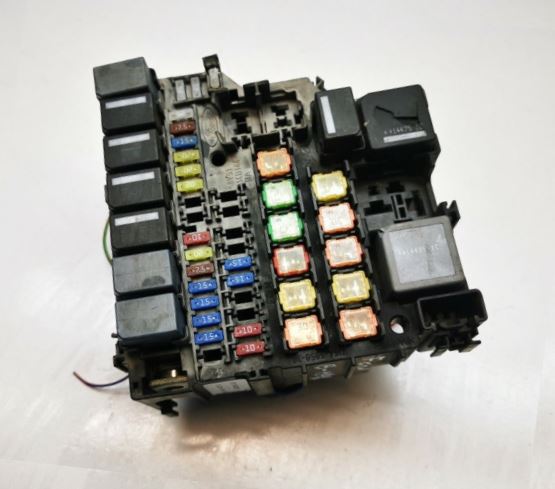
General view.
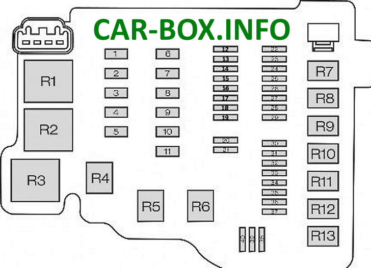
| Diagram | |
|---|---|
|
|
| № | Description |
| 1 | 30 / 40A Anti lock brake system, dynamic stability control module |
| 2 | 60A Cooling Fan - High Speed |
| 3 | 30 / 40A Cooling Fan - Low Speed |
| 4 | 30A Heater fan |
| 5 | 60A Passenger compartment fuse box power supply (battery) |
| 6 | 30A Body control unit |
| 7 | 60A Passenger compartment fuse box power supply (ignition) |
| 8 | 60A Glow plugs 50A DPS6 module |
| 9 | 40A Heated windshield |
| 10 | 40A Heated windshield |
| 11 | 30A Start Relay |
| 12 | 10A Relay high beam left headlight |
| 13 | 10A Relay high beam right headlight |
| 14 | 15A Auxiliary pump |
| 15 | 20A Ignition coil |
| 16 | 15A Powertrain control module, high and low speed cooling fan |
| 17 | 15A Heated oxygen sensors (gasoline engines) 20A Power supply module (diesel engines) |
| 18 | Reserve |
| 19 | 7.5A Air conditioning controller |
| 20 | Reserve |
| 21 | Reserve |
| 22 | 15A Battery power supply for lighting control |
| 23 | 15A Front fog lamps |
| 24 | 15A Direction indicators |
| 25 | 15A Outdoor lighting on the left side |
| 26 | 15A Exterior lighting on the right side |
| 27 | 7.5A Powertrain control module |
| 28 | 20A Anti-lock braking system, dynamic stability control |
| 29 | 10A A / C compressor clutch |
| 30 | Reserve |
| 31 | Reserve |
| 32 | 20A Buzzer, battery power saving function, no key module |
| 33 | 20A Heated rear window |
| 34 | 20A Fuel pump relay, diesel fuel heater |
| 35 | 15A Cat1 Alarm System |
| 36 | 7.5A Automatic transmission controller |
| 37 | 25A Left front door module |
| 38 | 25A Right front door module |
| 39 | 25A Left rear door module |
| 40 | 25A Right rear door module |
| R1 | Cooling fan |
| R2 | Reserve |
| R3 | Powertrain control module |
| R4 | High beam |
| R5 | Reserve |
| R6 | Reserve |
| R7 | Engine cooling fan motor |
| R8 | Starter |
| R9 | Air conditioning compressor clutch |
| R10 | Front fog lights |
| R11 | Fuel pump, diesel heater |
| R12 | Reversing light |
| R13 | Heater fan |
In the passenger compartment
Located under the dashboard on the driver's side.
Type 1
| Diagram | |
|---|---|

|
|
| № | Description |
| 1 | 7,5A Ignition, rain sensor, heated windshield |
| 2 | 10A Stop lights |
| 3 | 7,5A Lantern |
| 4 | 7.5A Headlight range correction |
| 5 | Reserve |
| 6 | 15A Rear window cleaner |
| 7 | 15A Washer pump |
| 8 | Reserve |
| 9 | 15A Heated passenger seat |
| 10 | 15A Heated driver's seat |
| 11 | Reserve |
| 12 | 10A Airbag module |
| 13 | 10A Ignition, electric power steering, instrument cluster, passive anti-theft system, anti-lock braking system |
| 14 | 7.5A Powertrain control module, gear lever, fuel pump |
| 15 | 7,5A Audio system, instrument cluster |
| 16 | 7.5A Heated windshield |
| 17 | Reserve |
| 18 | Reserve |
| 19 | 15A Block of information communication channel |
| 20 | 20A Multifunction display, clock, internal scanner, heating vents, air conditioning panel |
| 21 | 15A Audio system, navigation system, Bluetooth system |
| 22 | 7,5А Instrument cluster |
| 23 | 7,5А Trailer module |
| 24 | 7.5A Sync module antenna |
| 25 | Reserve |
| 26 | 30A Left front wiper |
| 27 | 30A Right front wiper |
| R1 | ignition relay |
Type 2
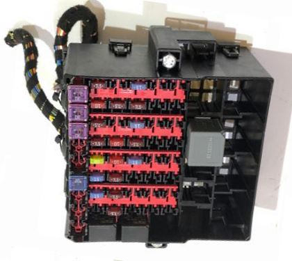
General view.
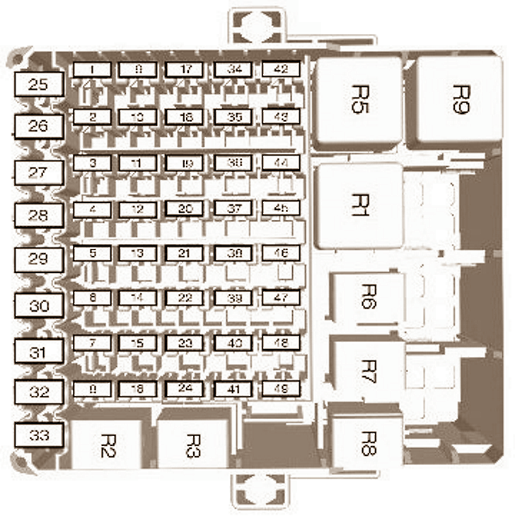
| Diagram | |
|---|---|
|
|
| № | Description |
| 1 | 7.5A Ignition, rain sensor, heated windshield, roof lamp, interior rearview mirror |
| 2 | 10A Stop lights |
| 3 | 7.5A Reversing light |
| 4 | 7.5A Headlight range correction |
| 5 | Reserve |
| 6 | 15A Rear window wiper |
| 7 | 15A Washer pump |
| 8 | Reserve |
| 9 | 15A Heated passenger seat |
| 10 | 15A Heated driver's seat |
| 11 | Reserve |
| 12 | 10A Airbag module |
| 13 | 10A Ignition, electric power steering, instrument cluster, passive anti-theft system, anti-lock braking system |
| 14 | 7.5A Powertrain Control Module, Transmission Lever, Fuel Pump |
| 15 | 7.5A Audio system, instrument cluster |
| 16 | 7.5A Heated windshield right |
| 17 | Reserve |
| 18 | Reserve |
| 19 | 10A Block of information communication channel |
| 20 | 20A Trailer module |
| 21 | 15A Audio system, navigation system |
| 22 | 7.5A Instrument cluster |
| 23 | 7.5A Multi-function display, clock, internal scanner, heating vents, air conditioning panel |
| 24 | 10A Sync Module |
| 25 | Reserve |
| 26 | 30A Left front wiper |
| 27 | 30A Right front wiper |
| 28 | 30A Voltage Regulation Module |
| 29 | 20A Rear electrical outlet |
| 30 | 20A Cigarette lighter Ford B-Max, front power socket |
| 31 | Reserve |
| 32 | Reserve |
| 33 | Reserve |
| 34 | 20A Keyless Access |
| 35 | 20A Keyless Access |
| 36 | 10A Block of information communication channel |
| 37 | 15A Ignition Switch |
| 38 | Reserve |
| 39 | Reserve |
| 40 | Reserve |
| 41 | Reserve |
| 42 | 7.5A Rear view camera |
| 43 | 10A Active City Stop Module |
| 44 | Reserve |
| 45 | Reserve |
| 46 | Reserve |
| 47 | Reserve |
| 48 | Reserve |
| 49 | Reserve |
| № | Relay assignment |
| R1 | Ignition |
| R2 | Cigarette lighter |
| R3 | Not used |
| R4 | Active City Stop Relay |
| R5 | Not used |
| R6 | Keyless entry (accessory) |
| R7 | Keyless entry (ignition) |
| R8 | Battery Discharge Prevention Relay |
| R9 | Heated windshield on the left side |
| R10 | Electric heated windscreen on the right side |
| R11 | Not used |
| R12 | Not used |
View and print PDF:
