Most of the power supply circuits of the electrical equipment of the American truck are protected by fuses. Powerful current consumers are connected via relays. Protective elements are installed in distribution boxes, which are located under the hood and in the passenger compartment.

The information provided in the diagrams is relevant for Ford Transit 6th generation models 2006, 2007, 2008, 2009, 2010, 2011, 2012, 2013, 2014 with gasoline and diesel engines.
In the engine compartment
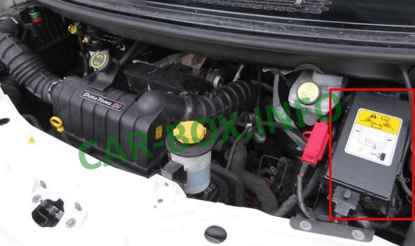
The main distribution box is located on the right side of the engine compartment.
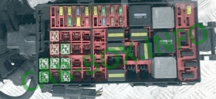
General view.
| Diagram | ||
|---|---|---|

|
||
| № | Description | A |
| 1 | Mechanical transmission ASM | 5 |
| 2 | Spare | |
| 3 | Daytime running lights, low beam | 20 |
| 4 | Battery voltage sensor (diesel engines) | 5 |
| 5 | Fuel switch | 20 |
| 6 | Towing equipment | 30 |
| 7 | Sound signal | 15 |
| 8 | ABS (ABS brakes) | 20 |
| 9 | High beam headlights | 20 |
| 10 | Air conditioner | 10 |
| 11 | Windshield washers, rear window washers | 20 |
| 12 | Spare | |
| 13 | Multi-function lever, windshield wipers | 30 |
| 14 | Reversing lights | 15 |
| 15 | Engine immobilizer control module | 5 |
| 16 | Electronic engine control | 5 |
| 17 | Towing equipment | 30 |
| 18 | Spare | |
| 19 | Mechanical transmission ASM | 5 |
| 20 | Mechanical transmission ASM | 15 |
| 21 | Engine management | 20 |
| 22 | Gasoline pump | 20 |
| 23 | Dipped headlights, right side | 10 |
| 24 | Dipped headlights, left side | 10 |
| 101 | ABS | 40 |
| 102 | Heated windshield, left side | 40 |
| 103 | Main power supply of the electrical system | 50 |
| 104 | fifty | |
| 105 | Engine cooling fan (2.0 l diesel engines and 2.3 l DOHC engines) | 40 |
| 106 | Ignition | 30 |
| 107 | ||
| 108 | Spare | |
| 109 | Engine cooling fan (2.0 l diesel engines and 2.3 l DOHC engines) | 40 |
| 110 | Heated windshield, right side | 40 |
| 111 | Ignition | 30 |
| 112 | Spare | |
| 113 | Mechanical transmission ASM | 40 |
| 114 | Active suspension compressor relay | 30 |
| 115 | Spare | |
| 116 | Spare | |
| 117 | Spare | |
| 118 | Spare | |
| 119 | Spare | |
| 120 | Spare | |
| 121 | Spare | |
| 122 | Spare | |
| Relay assignment | ||
| R1 | starter | |
| R2 | Glow plug relay | |
| Cooling fan relay | ||
| R3 | horn | |
| R4 | High beam relay | |
| R5 | generator | |
| R6 | low beam headlights | |
| R7 | Engine control relay | |
| R8 | Relay for checking the health of lamps (cars without ABS) | |
| R9 | TDdi: Fuel pump relay TDci: Injector module |
|
| R10 | Air conditioning relay (fully open throttle position) | |
| R11 | Low pressure fuel pump relay | |
| R12 | Cooling fan | |
| R13 | Ignition | |
| Diodes | ||
| D1 | - | |
| D2 | - | |
| D3 | Trailer connector or A / C compressor coupling | |
| D4 | Trailer connector or A / C indicator | |
| Under the fuse box there is an additional. block with relay modules. | ||
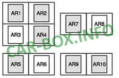
|
||
| AR1 | Towing equipment | |
| AR2 | Right direction indicator (depending on model variant) | |
| AR3 | No | |
| AR4 | Left turn signal (depending on model variant) | |
| AR5 | High speed cooling fan (vehicles with 2.4L diesel engines and rear air conditioning) | |
| AR6 | No | |
| AR7 | High speed cooling fan (2.0L diesel engines and DOHC engines) | |
| AR8 | No | |
| AR9 | Manual transmission with automatic gear shifting | |
| AR10 | ||
In the cabin
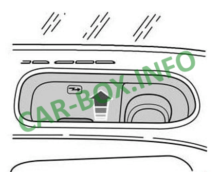
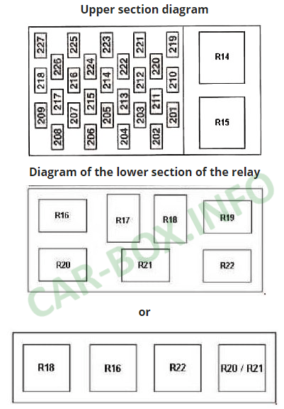
The main distribution box is located under the stowage compartment on the passenger side, in the instrument panel. To access it, you need to lift the glove compartment case using the handle.

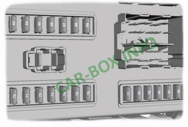
An additional distribution box is located under the driver's seat.
| Diagram of the main cabin block Ford Transit 6 | |
|---|---|
|
|
| № | Description |
| 201 | 15A Instrument panel, rear window wiper, clock |
| 202 | 5A Heated windshield |
| 203 | 20A Fog lights / lights |
| 204 | Reserve |
| 205 | 15A Lighting control, direction indicators, multifunction lever, engine control, ignition |
| 206 | 5A License plate illumination lamp |
| 207 | 10A Airbag module |
| 208 | 10A Illumination of the instrument panel |
| 209 | 15A Side lights |
| 210 | 15A Tachometer, hours |
| 211 | 30A Rear heater fan motor |
| 212 | 10A Cigarette lighter |
| 213 | 10A Rear air conditioning |
| 214 | 15A Interior lighting, power mirrors |
| 215 | 20A Heated windshield, heated front seats, additional heater |
| 216 | 20A Power sockets for connecting additional equipment |
| 217 | 15A Heated rear window, heated exterior mirrors |
| 218 | Reserve |
| 219 | 30A Power windows |
| 220 | 20A Heated rear window |
| 221 | 15A Brake light switch |
| 222 | 15A Audio system |
| 223 | 30A Heater fan motor |
| 224 | 20A headlight switch |
| 225 | 15A Air conditioner |
| 226 | 20A Hazard warning lights, direction indicators |
| 227 | 5A Audio system, ABS |
| Relay | |
| R14 | Wiper relay |
| R15 | Relay for auxiliary ignition circuits |
| R16 | Heated windshield relay, right side |
| R17 | Rear door buzzer |
| R18 | Interior lighting |
| R19 | Rear door buzzer |
| R20 | Windshield heater relay, left side (timer relay) |
| R21 | Rear wiper relay |
| R22 | Heated rear window, mirrors relay |
| Fuse diagram of the additional block under the driver's seat | ||
|---|---|---|
|
||
| № | Description | A |
| 63 | Reverse parking assist, rain sensor | 5 |
| 64 | Accelerator Pedal Position Sensor | 2 |
| 65 | Brake light switch | 15 |
| 66 | Instrument panel, power supply of the PATS security system, tachograph, control panel backlight | 5 |
| 67 | Washer pump | 15 |
| 68 | Restraint systems control unit | 10 |
| 69 | External lighting switch (KL15) | 20 |
| 70 | Sonar with emergency power supply | 20 |
| 71 | External lighting switch (KL30) | 5 |
| 72 | Power supply for the battery power consumption regulator, OBDII (KL30) | 10 |
| 73 | Power supply for audio and navigation systems and mobile phone | 15 |
| 74 | Instrument panel, auxiliary heater timer, keyless entry system power supply, interior motion sensor (KL30) | 5 |
| 75 | Side lights on the right side | 7.5 |
| 76 | Side lights on the left side | 7.5 |
| 77 | Ignition switch power supply, battery disconnection sensor coil power supply | 5 |
| 78 | Centralized locking system | 15 |
| 79 | License plate light, side marker lights | 7.5 |
| 80 | Front fog lights | 15 |
| 81 | Rear fog lights | 10 |
| 82 | Regular power supply of the audio unit and instrument panel | 3 |
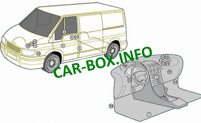
General arrangement
Location of the electronic control units.
|
|
| 1 | Air conditioner electronic control unit |
| 2 | Anti-theft control unit |
| 3 | Anti-theft alarm horn 1 |
| 4 | Anti-theft alarm horn 2 |
| 5 | Additional heater - bottom (if any) |
| 6 | Additional heater control unit - if installed |
| 7 | Battery - under the seat |
| 8 | Central locking control unit - in the anti-theft system control unit |
| 9 | Diagnostic connector (DLC) |
| 10 | Fuse / relay box, engine compartment 1 |
| 11 | Fuse / relay box, engine compartment 2 |
| 12 | Fuse / relay box, engine compartment 3 |
| 13 | Fuse / relay box dashboard 1 |
| 14 | Fuse / relay box dashboard 2 |
| 15 | Additional fuse (15A), anti-theft system control unit |
| 16 | Additional fuse (15A), anti-theft system control unit |
| 17 | Additional fuse (40A), engine management system - near the battery |
| 18 | Additional fuse (70 / 80A), engine management system - near the battery |
| 19 | Heater / A / C blower motor relay |
| 20 | Heater blower motor resistor, front |
| 21 | Heater blower motor resistor, rear |
| 22 | Sound signal |
| 23 | Relay - gate indicator interrupter |
| 24 | Inertia Fuel Cut Off Switch - If Equipped |
| 25 | Parking system control unit |
| 26 | SRS electronic control unit |

All fuse diagram shown are confusing
My under the glove box fuse cover cover no's are F38,F39ect up to F62..
Everything you show is different no's and codes like 222...I wantro change the audio fuse as the radio don't work. So I don't know the F code fuse?? Thanks