
The 5th-generation Ford Transit (chassis code VE83) was produced from 1994 to 1999. This guide details the locations, circuit diagrams, and component descriptions for the fuse and relay blocks in these vehicles. The fuse protecting the “Cigarette lighter” circuit is highlighted in bold.
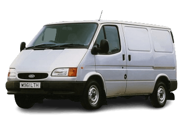
This model features three main fuse and relay distribution boxes. The primary fuse panel is located in the passenger compartment, with two additional high-current and auxiliary boxes situated in the engine compartment. The exact layout, amperage ratings, and number of populated circuits may vary depending on the trim level and optional equipment of your specific Ford Transit.
Passenger Compartment Fuse Panel
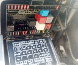
This central fuse panel is located beneath the dashboard on the driver's side, concealed behind a protective cover. The specific fuse and relay diagram for your vehicle is printed on the reverse side of this cover.
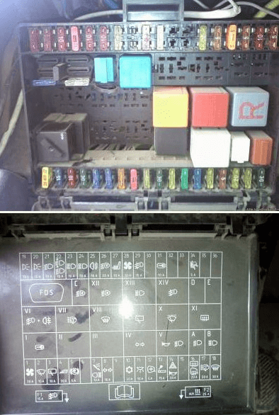
An example of this fuse panel is shown below.
| Diagram | |
|---|---|
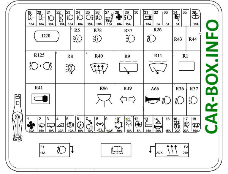
|
|
| No. | Description |
| 1 | 30A Blower motor |
| 2 | 15A Windshield wipers |
| 3 | 10A Rear window wiper |
| 4 | 30A Power windows |
| 5 | 5A Anti-lock Braking System (ABS) |
| 6 | 10A Traction control system, cold start system, clock, ABS, charging system, headlights, instrument cluster, headlight leveling system, anti-theft system |
| 7 | 10A Brake lights |
| 8 | 10A Turn signals |
| 9 | 10A Anti-theft alarm system |
| 10 | 30A Air conditioning (A/C) |
| 11 | 10A Interior lighting |
| 12 | 5A Power mirrors |
| 13 | 15A Cigarette lighter / Power point |
| 14 | 25A Hazard warning lights, horn |
| 15 | 15A Anti-theft alarm system, siren |
| 16 | 20A Heated rear window |
| 17 | 20A Headlight washer pump |
| 18 | 30A Heated windshield |
| 19 | 10A Right parking lights |
| 20 | 10A Left parking lights |
| 21 | 10A Right headlight (low beam) |
| 22 | 10A Left headlight (low beam) |
| 23 | 10A Right headlight (high beam) |
| 24 | 10A Left headlight (high beam) |
| 25 | 10A Rear fog lights |
| 26 | 15A Daytime Running Lights (DRL) |
| 27 | 10A Heated front seats |
| 28 | 10A Auxiliary electric heater |
| 29 | 15A Front fog lights |
| 30 | Spare |
| 31 | 10A Ignition switch |
| 32 | 5A Passive Anti-Theft System (PATS) |
| 33 | 5A Passive Anti-Theft System (PATS) |
| 34 | 5A Supplemental Restraint System (SRS) / Airbags |
| 35 | 5A Door courtesy lights, SRS / Airbags |
| 36 | 10A Windshield wipers and washer pump |
| R1 | Heated rear window relay |
| R5 | Daytime Running Lights (DRL) relay |
| R8 | Headlight washer pump relay |
| R9 | Rear window wiper relay |
| R11 | Windshield wiper relay |
| R26 | Front fog lights relay |
| R36 | Low beam headlight relay |
| R37 | High beam headlight relay |
| R39 | Turn signal / hazard flasher relay |
| R40 | Heated windshield relay |
| R41 | Ignition relay |
| R43 | Left turn signal / hazard relay |
| R44 | Right turn signal / hazard relay |
| R78 | Low beam headlight relay |
| R79 R5 | Low beam headlight relay |
| R80 | Daytime Running Lights (DRL) relay |
| R96 | Interior lighting battery saver relay |
| R125 | Rear fog light relay |
| A66 | Lighting control module warning chime |
| D20 | Data Link Connector (DLC) / OBD-II Port |
| Fuse No. 13 (15A) protects the Ford Transit cigarette lighter circuit. | |
Engine Compartment Fuse Boxes
High-Current Fuse Panel
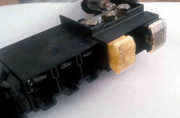
This primary power distribution box is located on the right side of the engine compartment (passenger side), positioned behind the main battery near the right fender. The vehicle's main electrical loads are routed through these fusible links. The box accommodates up to six high-current fuses, designated FA through FF. The specific wiring diagram is printed on the unit's cover.
Regardless of the engine type or trim level, all 5th-generation Ford Transit models will have a minimum of two populated fuses in this panel.
| FA | 80A Starter motor circuit, 2.0L DOHC engine management system, exterior lighting system |
| FB | 40A Front fog lights, auxiliary heater |
| FC | 60A Hazard warning system, engine management system |
| FD | 50A Anti-lock Braking System (ABS), Electronic Stability Program (ESP) |
| FE | 50A Engine Control Module (ECM) (gasoline), or glow plug/cold start system (diesel) |
| FFa | 20A Engine management system (diesel), air conditioning (A/C) |
| FFb | 50A 2.0L DOHC / Turbodiesel: Automated manual transmission clutch, engine management system |
| FFc | 60A Automated manual transmission clutch, engine management system, air conditioning (A/C) |
Auxiliary Fuse and Relay Box
This secondary box is located on the left side of the engine compartment. Its specific layout diagram is printed on the inside of the cover. It typically houses the following components:
Fuses protecting the automated clutch and A/C condenser fan circuits
- R22 - Starter motor relay
- R84 - Powertrain / Engine control relay
- R124 - A/C condenser fan relay
- R209 - Hydraulic pump relay
