The 8th generation Ford Transit was produced in 2013, 2014, 2015, 2016, 2017, 2018, 2019, 2020, 2021 with gasoline and diesel engines.

During this time, he went through a restyling. Ford Transit Custom / Tourneo Custom provides the mid-size light-duty Ford Transit series. In our material you will find a description of the 8th generation Ford Transit fuse and relay blocks, block diagrams and their location. The fuse responsible for the “Cigarette lighter” is highlighted in bold.+
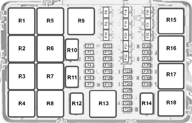
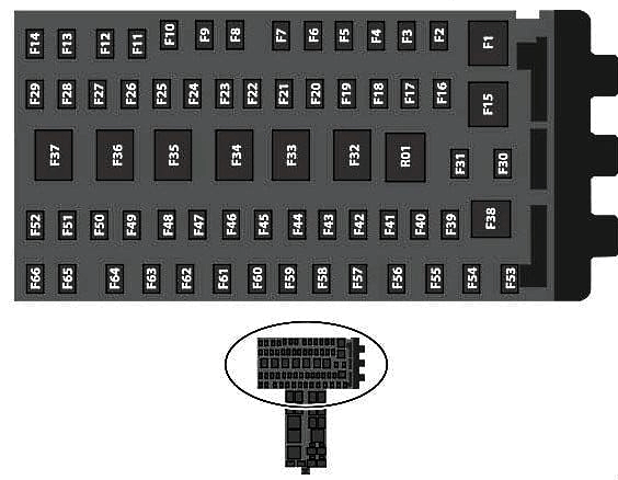
In engine compartment

Fuse box located next to the washer fluid barrel, under the protective cover.
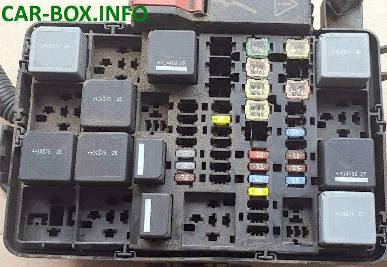
Example of execution
| Diagram | |
|---|---|
|
|
| Type 1 | |
| № | Description |
| F1 | 10A System for reducing toxicity of exhaust |
| F2 | 15A Exhaust toxicity reduction system |
| F3 | 15A Exhaust toxicity reduction system |
| F4 | 10A System for reducing toxicity of exhaust |
| F5 | 30A Diesel flue gas filter evaporator, Glow plug control system |
| F6 | 3A Anti-lock braking system. Maintaining stability. Ignition |
| F7 | 7.5A Powertrain control module |
| F8 | 20A Cooling fan |
| F9 | 30A Left windshield wiper |
| F10 | 30A Right windshield wiper |
| F11 | 10A Air conditioning compressor clutch |
| F12 | 20A Glow plug of the evaporator of the filter of combustion products of diesel fuel |
| F13 | Reserve |
| F14 | 30A Emission control system - ignition |
| F15 | Not used |
| F16 | Not used |
| F17 | Not used |
| F18 | 40A Anti-lock braking system, stability control pump |
| F19 | 30A starter solenoid |
| F20 | 60A Glow plugs |
| F21 | 60A Ignition Relay 3 |
| F22 | Reserve |
| F22 | Reserve |
| F23 | Reserve |
| F24 | 7.5A High pressure fuel pump |
| F25 | Reserve |
| F26 | Reserve |
| F27 | Reserve |
| F28 | Reserve |
| F29 | Reserve |
| F30 | 40A Fan 1 cooling system |
| F31 | 40A Fan 2 cooling system |
| F32 | 60A Electric motors (two) windscreen wipers |
| F33 | 20A Start-stop of auxiliary water pump |
| F34 | Reserve |
| F35 | 15A Power supply for the powertrain control system |
| F36 | 15A NOXI sensor 2 |
| F37 | 7.5A Volume control valve |
| F38 | 7.5A Mass air flow sensor |
| F39 | 15A Diesel pump fuel vaporizer |
| Relay | |
| R1 | Ignition |
| R2 | Starter |
| R3 | Rear window wiper |
| R4 | Not used |
| R5 | cooling Fan |
| R6 | Windshield wiper - on and off |
| R7 | Windshield wiper - low and high speed |
| R8 | Not used |
| R9 | Not used |
| R10 | Air conditioning compressor clutch |
| R11 | Evaporator System Fuel Glow Plug |
| R12 | High pressure fuel pump |
| R13 | All wheel drive pump |
| R14 | Econetic system |
| R15 | Cooling fans: high speed and low speed |
| R16 | Exhaust emission control system |
| R17 | Powertrain control module |
| R18 | Cooling Fan - High Speed |
| Type 2 | |
| № | Description |
| F1 | 5A Mute the radio |
| F2 | Reserve |
| F3 | Reserve |
| F4 | Reserve |
| F5 | Reserve |
| F6 | 15A Nitrogen oxide sensor |
| F7 | 15A Particulate Sensor |
| F8 | 20A High speed cooling fan |
| F9 | Reserve |
| F10 | Reserve |
| F11 | Reserve |
| F12 | Reserve |
| F13 | Reserve |
| F14 | Reserve |
| F15 | Reserve |
| F16 | Reserve |
| F17 | Reserve |
| F18 | 40A Cooling fan 2 |
| F19 | 40 / 60A cooling fan |
| F20 | 40A emission control system |
| F21 | 40A Glow plug 2 |
| F22 | 40A Glow plug 1 |
| F23 | 10A Air conditioning compressor clutch |
| F24 | Reserve |
| F25 | 15A Right headlamps with high intensity discharge lamps |
| F26 | 15A Left headlights with high intensity discharge lamps |
| F27 | Reserve |
| F28 | 5A Positive crankcase ventilation valve heating element |
| F29 | 7,5 / 15A Coolant pump |
| F30 | 40 / 60A Powertrain control module relay |
| F31 | 20A Relay "run-start" 2 |
| F32 | 20A Fuel-fired auxiliary heater |
| F33 | Reserve |
| F34 | Reserve |
| F35 | 20A Powertrain control module |
| F36 | 20A Power wire 5 car |
| F37 | 15A Reagent tank. Exhaust Gas Recirculation Valve |
| F38 | 10A High speed cooling fan. Air conditioning compressor clutch. Low speed cooling fan. Relay for high speed and low speed cooling fan. Relay coils R1, R5, R10, and R15 of the engine electrical box |
| F39 | Glow plug control system |
| Relay | |
| R1 | High speed cooling fan |
| R2 | Not used |
| R3 | Rear window wiper |
| R4 | Air suspension module |
| R5 | Cooling Fan |
| R6 | Not used |
| R7 | Left-hand HID headlamps |
| R8 | Right-hand headlights with high intensity discharge lamps |
| R9 | Starter |
| R10 | Air conditioning compressor clutch |
| R11 | Not used |
| R12 | Not used |
| R13 | Emission Reduction Catalyst |
| R14 | Not used |
| R15 | Low speed cooling fan |
| R16 | Not used |
| R17 | Not used |
| R18 | Powertrain control module |
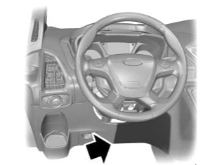
In passenger compartment
Inside the Ford Transit mk8, there are 3 fuse and relay boxes. 2 under the dashboard on the driver's side and one behind the back of the driver's seat.
Under the panel
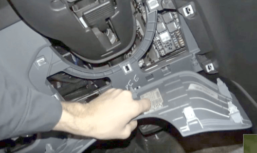
Remove the protective cover to access it.
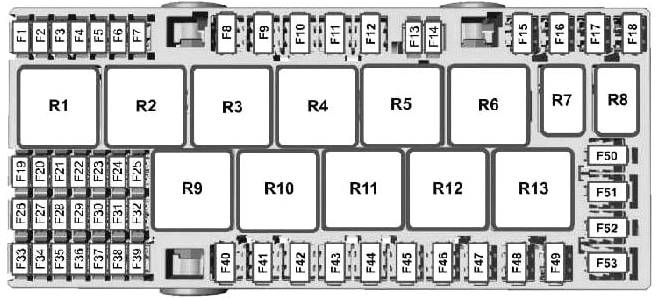
Type 1
Fuse and relay box
| Diagram | |
|---|---|
|
|
| № | Appointment |
| F1 | 10A Airbag module |
| F2 | 20A Heated rear window |
| F3 | 10A Heated exterior mirrors |
| F4 | Reserve |
| F5 | Reserve |
| F6 | 5A Tachograph |
| F7 | 10A Battery sensor |
| F8 | 40A AC power outlet |
| F9 | Reserve |
| F10 | 30A Power driver's seat |
| F11 | 30A Electric passenger seat |
| F12 | 30A threshold illumination |
| F13 | Reserve |
| F14 | 5A Tracking and blocking control module |
| F15 | 40A Battery relay of the powertrain control module |
| F16 | 40A Power relay powertrain control module |
| F17 | Reserve |
| F18 | 30A Anti-lock brake system valves. Stability control valves |
| F19 | 5A Tachograph |
| F20 | 5A Heated outside mirror relay. Heated windshield relay |
| F21 | Reserve |
| F22 | 15A Passenger compartment fuse box |
| F23 | 7.5A Air conditioning control module |
| F24 | 5A Headlight range correction |
| F25 | 7.5A Interior lighting |
| F26 | 10A Heated exterior mirrors |
| F27 | 20A Heated front seats |
| F28 | 20A Direction indicators |
| F29 | Rear parking aid camera. Control system for compliance with road markings. Power Mirrors |
| F30 | Adaptive cruise control system |
| F31 | Reserve |
| F32 | 10A Interior lighting |
| F33 | 20A All-wheel drive module |
| F34 | 20A Rear window wiper |
| F35 | 5A Power folding mirrors |
| F36 | 20A Buzzer |
| F37 | 7.5A SYNC module |
| F38 | 5A Electro blower fan. Horn relay. Windshield wiper relay |
| F39 | 7.5A Remote keyless entry. Accumulator battery. Electric windows. Heating, ventilation and air conditioning of the rear passenger area |
| F40 | 40A Front blower motor |
| F41 | 40A Rear blower motor |
| F42 | 30A Heated rear window |
| F43 | 30A Trailer power socket |
| F44 | 60A Additional power sockets |
| F45 | Reserve |
| F46 | 30A Windows with electric drive |
| F47 | 20A Cigarette lighter fuse Ford Transit |
| F48 | 20A Rear auxiliary power sockets |
| F49 | 20A Front auxiliary power sockets |
| F50 | 60A Ignition relay 1 |
| F51 | 60A Ignition Relay 2 |
| F52 | 40A Heated windshield (left side) |
| F53 | 40A Heated windshield (right side) |
| Relay | |
| R1 | Fuel-fired auxiliary heater |
| R2 | Additional power sockets |
| R3 | Not used |
| R4 | Ignition 2 |
| R5 | Electric windows |
| R6 | Ignition 1 |
| R7 | Sound signal |
| R8 | Not used |
| R9 | Front blower motor |
| R10 | Rear blower motor |
| R11 | Heated rear window. Heated exterior mirrors |
| R12 | Heated windshield (left side) |
| R13 | Heated windshield (right side) |
| For the operation of the Ford Transit cigarette lighter and additional power sockets and USB port, fuses 47, 48, 49 at 20A are responsible. | |
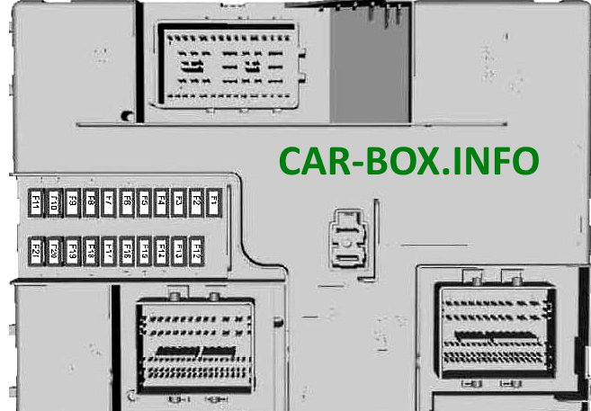
Additional fuse box
| Diagram | |
|---|---|
|
|
| № | Designation |
| F1 | 15A Central locking system 2 |
| F2 | 15A Centralized locking system 1 |
| F3 | 15A Ignition lock (switch) Additional battery relay |
| F4 | 5A Parking aid module |
| F5 | 5A Rain sensor module. Automatic light control module |
| F6 | 15A Windshield washer pump |
| F7 | 7.5A Exterior mirrors |
| F8 | 15A Front fog lamps |
| F9 | 10A Right high beam relay |
| F10 | 10A Left high beam relay |
| F11 | 25A Outdoor lights on the right side. Side lights on the left side |
| F12 | 20A Anti-theft alarm. Battery standalone audio device |
| F13 | 15A Data connector. Relay for auxiliary power socket. Interior lighting |
| F14 | 25A Daytime running lights Direction indicators Rear fog lights |
| F15 | 25A Side lights on the right side. Outdoor lights on the left. Central brake light |
| F16 | 20A Audio controls |
| F17 | 7.5А Heater control system. Instrument panel Blower fan |
| F18 | 10A Headlight switch. Steering wheel module |
| F19 | 5A Reset Front Controls Display Interface Module |
| F20 | 5A Passive anti-theft system and ignition. Ignition |
| F21 | 3A Front audio control module. Auxiliary relay |
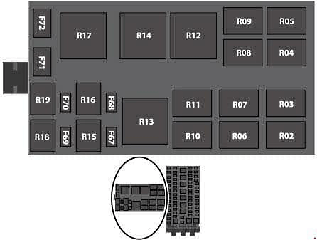
Type 2

Fuse and relay box - Execution example
Location
| Diagram | |
|---|---|
|
|
| № | Decoding |
| F1 | 60A Windshield wiper motor relay |
| F2 | 40A Electric blower fan |
| F3 | Reserve |
| F4 | 40A Heated rear window. Heated exterior mirrors |
| F5 | 40A Trailer power supply B + |
| F6 | 40A Auxiliary power socket 2 |
| F7 | 40A Auxiliary power socket 1 |
| F8 | 20A Buzzer |
| F9 | 15A Rear window washer relay |
| F10 | 10А Relay coils R1, R2, R3, R4, R5, R10, R17 |
| F11 | Reserve |
| F12 | Reserve |
| F13 | 20A Cigarette lighter |
| F14 | 20A Auxiliary power socket on the instrument panel |
| F15 | 50A Voltage quality module. Body control unit |
| F16 | 25A Anti-lock braking system module. Electronic Stability Control Valves |
| F17 | 5A Battery positive voltage relay coil of the powertrain control module |
| F18 | 10A Stop light |
| F19 | 15A Load interlock relay |
| F20 | 5A Additional fuel-fired heater |
| F21 | 15A Automatic transmission control unit |
| F22 | 25A Oil pump for automatic transmission |
| F23 | 20A Heated rear window left side |
| F24 | 10A Heated exterior mirrors |
| F25 | 7.5A Unlock driver's door |
| F26 | 7.5A Unlocking the passenger door |
| F27 | Reserve |
| F28 | Reserve |
| F29 | 40A Rear blower motor |
| F30 | 20A Rear auxiliary power socket |
| F31 | 20A Heated rear window left side |
| F32 | 60A Relay "run / start" |
| F33 | 60A Fuel pump relay |
| F34 | 40A Heated rear window left side |
| F35 | 40A Heated rear window right side |
| F36 | 50A Power supply RP1 body control unit |
| F37 | 50A Power supply RP2 to the body control unit |
| F38 | 60A Power BB4 standard relay box |
| F39 | 20A Heated seats |
| F40 | 5A Ignition unit of the powertrain control module |
| F41 | 5A Fuel fired auxiliary heater relay coil |
| F42 | 5A Headlight range correction |
| F43 | 5A Transmission control module |
| F44 | 10A Air suspension. Voltage quality module. Climate control system for rear passengers' zone. Light and distance detection system. Front and rear view cameras. Adaptive cruise control system |
| F45 | 20A Direction indicators |
| F46 | 5A Heated rear window. Heated outside mirror relay |
| F47 | 5A Anti-lock brake system module |
| F48 | 10A Camper Interface Connector 1 |
| F49 | 20A Rear window wiper |
| F50 | 5A Rain sensor module. Rear window wiper |
| F51 | 25A Windshield wiper motor |
| F52 | 25A Windshield wiper motor |
| F53 | Reserve |
| F54 | Reserve |
| F55 | 40A Anti-lock braking system module. Electronic stability control system |
| F56 | 30A Threshold with electric drive |
| F57 | 30A Power driver's seat |
| F58 | 20A Front fog lamp |
| F59 | 30A starter solenoid |
| F60 | 15A Trailer battery charge |
| F61 | 15A Left side double interlock |
| F62 | 15A Right side of double interlock |
| F63 | 15A Left side of central locking |
| F64 | 15A Right side of central locking |
| F65 | 20A Fuel pump |
| F66 | 40A Heated Fuel Filter |
| Relay box | |
|---|---|
|
|
| Circuit breakers | |
| F67 | Reserve |
| F68 | Reserve |
| F69 | 7.5A Tachograph |
| F70 | Reserve |
| F71 | 40A 230V socket |
| F72 | 30A Trailer power socket |
| Relay | |
| R1 | Sound signal |
| R2 | Heated rear window |
| R3 | Rear blower motor |
| R4 | Rear auxiliary power outlets |
| R5 | Cigarette lighter. Additional power socket |
| R6 | Heated windshield relay (left side) |
| R7 | Heated windshield relay (right side) |
| R8 | Rear window washer pump |
| R9 | Fuel-fired booster heater blower fan |
| R10 | Blower fan |
| R11 | External blocking |
| R12 | Power folding mirrors |
| R13 | Work-start |
| R14 | Fuel pump |
| R15 | Not used |
| R16 | Not used |
| R17 | Windshield wiper |
| R18 | Front fog lamp |
| R19 | Not used |
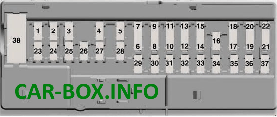
Auxilary fuse panel
Location.
| Diagram | |
|---|---|
|
|
| № | Appointment |
| 1 | Reserve |
| 2 | 7.5A Exterior mirrors with electric drive. Driver's door window |
| 3 | 20A Unlocking the driver's door. Unlocking the passenger door |
| 4 | Reserve |
| 5 | Reserve |
| 6 | Reserve |
| 7 | Reserve |
| 8 | 10A Anti-theft alarm horn |
| 9 | Spare. |
| 10 | Spare. |
| 11 | 5A Intrusion sensor. Heating, ventilation and air conditioning of the rear passenger area |
| 12 | 7,5А Microclimate control system. Hazard warning light button |
| 13 | 7.5A Steering column. Dashboard. Data connector |
| 14 | Spare |
| 15 | 10A Data Connector |
| 16 | 15A Sliding door lock actuator |
| 17 | 5A Battery stand-alone sound device |
| 18 | 5A Ignition lock (switch) |
| 19 | 7.5A Passenger airbag deactivation indicator. Passenger airbag deployment switch. |
| 20 | 7.5A Tachograph |
| 21 | 5A Additional heater control module |
| 22 | 5A Spare |
| 23 | 10A Delay off auxiliary equipment. DC / AC inverter |
| 24 | 30A Centralized locking system. Double locking system |
| 25 | 30A Driver's door module |
| 26 | 30A Passenger door module |
| 27 | 30A Spare |
| 28 | 20A Spare |
| 29 | 30A Spare |
| 30 | 30A Spare |
| 31 | 15A Spare |
| 32 | 10A SYNC module. Multifunctional display. RF radio receiver |
| 33 | 20A Audio system. SYNC module |
| 34 | 30A Ignition relay. Active parking assist control module. Heater control system. Control system for compliance with road markings. Airbag and seatbelt system control module. Central control unit. Passenger airbag deactivation indicator. Tachograph. Additional heater. Steering wheel module |
| 35 | 5A Airbag and seat belt control module |
| 36 | 15A Active parking assist control module. Control system for compliance with road markings. Steering wheel module |
| 37 | 20A Spare |
| 38 | 30A Windows with electric drive |
Fuse box behind the driver's seat
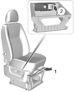
To access the distribution box, you must move the seat forward.
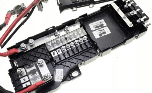
Photo - an example of execution
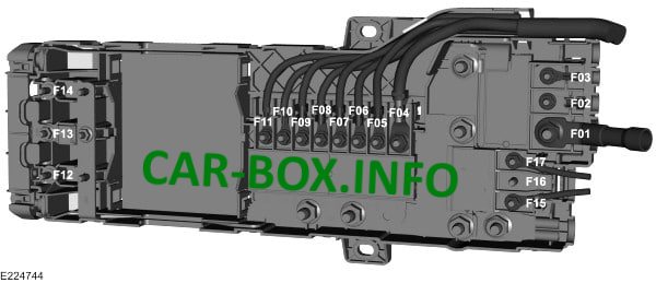
Consists of a high power fuse section and an internal fuse and relay section.
| Diagram | |
|---|---|
|
|
| № | Designation |
| F1 | 470A Fuse box in the engine compartment. Starter Generator |
| F2 | 100A Body systems control unit |
| F3 | 40A DC Inverter |
| F4 | 200A Power supply for 1 auxiliary relay box or Fuse box in the passenger compartment |
| F5 | 100A Power supply for 2 auxiliary relay boxes or Passenger compartment fuse box |
| F6 | 100A Additional heater |
| F7 | 80A Windshield heating relay |
| F8 | 100A Body systems control unit. Power supply 5 auxiliary relay box |
| F9 | 100A Power supply for 3 auxiliary relay boxes |
| F10 | 100A Power supply for 4 auxiliary relay boxes 60A Power supply for the fuse box in the passenger compartment |
| F11 | 100A Powertrain control module relay 60A Passenger compartment fuse box power |
| F12 | 60A Connection to a converted vehicle |
| F13 | 60A Connection to a converted vehicle |
| F14 | 60A Connection to a converted vehicle |
| F15 | 60A Climate control system for rear passengers |
| F16 | 100A Reserve |
| F17 | 60A Connection to a converted vehicle |
| Internal department diagram | |
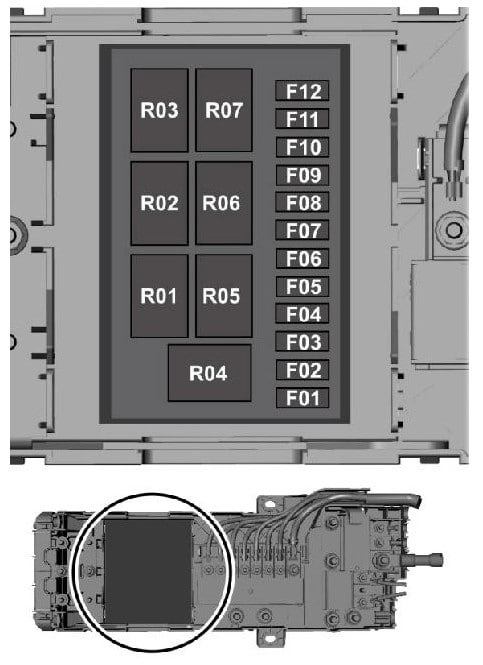
|
|
| F1 | 3A Outdoor lighting switch. Water heater switch. Power switch for connecting additional equipment |
| F2 | 20A Power supply |
| F3 | 20A Power supply R1 |
| F4 | 20A Power supply R2 |
| F5 | 15A Power supply R3 |
| F6 | 15A Power supply R4 |
| F7 | 15A Power supply R5, R6 |
| F8 | 10A Power supply R7 |
| F9 | 20A Radio transmitter |
| F10 | 5A Ignition lock (switch) relay |
| F11 | 15A Ignition lock (switch) relay |
| F12 | Reserve |
| Relay | |
| R1 | Beacon relay |
| R2 | Ignition relay |
| R3 | Auxiliary power socket 2. Water heater |
| R4 | Relay for interior lighting |
