The 1st generation Ford Mondeo was produced in 1992, 1993, 1994, 1995 and 1996 with sedan, five-door hatchback and five-door station wagon bodies. In this publication, we will show the location of all electronic control units, describe in detail the purpose of the fuses and relays Ford Mondeo 1 , as well as their photos and block diagrams in which they are located. The fuse responsible for the “Cigarette lighter” is highlighted in bold.
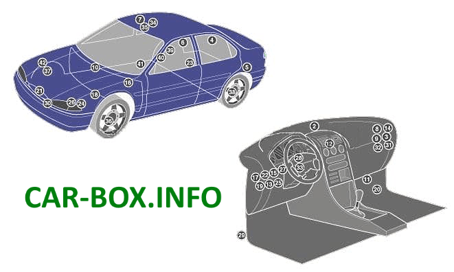
General arrangement
Location of electronic control units.
|
|
| № | Description |
| 1 | SRS electronic control unit |
| 2 | Anti-theft LED |
| 3 | Anti-theft control unit |
| 4 | Anti-theft alarm system - station wagon |
| 5 | Anti-theft alarm horn - sedan |
| 6 | Volume change sensor 1 (anti-theft system) |
| 7 | Volume change sensor 2 (anti-theft system) |
| 8 | Anti-theft alarm relay 1 |
| 9 | Anti-theft alarm relay 2 |
| 10 | Audible warning signal |
| 11 | Audio system output amplifier |
| 12 | Fault indication system add-on unit |
| 13 | Lamp health check system unit |
| 14 | Central locking / anti-theft control unit |
| 15 | Integrated relay / control unit |
| 16 | Cruise control (cruise control) control unit |
| 17 | Cruise control relay |
| 18 | Daylight Resistor |
| 19 | Diagnostic line - additional warning system |
| 20 | Diagnostic line - door locks |
| 21 | Cooling fan motor resistor |
| 22 | Fog lamp relay |
| 23 | Fuel pump |
| 24 | Fuse / relay box, engine compartment |
| 25 | Fuse / relay box, instrument panel |
| 26 | Glow plug timer relay |
| 27 | Headlight washer / washer relay |
| 28 | Indicator / Hazard Relay |
| 29 | Inertial fuel cut-off switch |
| 30 | Ambient temperature sensor |
| 31 | Rear window wiper intermittent relay |
| 32 | Seat heater relay |
| 33 | Steering wheel position sensor |
| 34 | Sunroof drive motor |
| 35 | Relay for electric sunroof |
| 37 | active suspension drive valve, right front |
| 39 | active suspension drive valve, right rear |
| 40 | Suspension control unit |
| 41 | Active suspension diagnostic connector |
| 42 | Throttle valve motor (traction control) |
In the passenger compartment

It is located under the driver's side dashboard.
| Diagram | |
|---|---|

|
|
| № | Purpose of fuses |
| 19 | 7,5A Electric door mirrors |
| 20 | 10A Windshield Wiper / Washer, Rear Window Washer Wiper |
| 21 | 30A / 40A Power windows, electric sunroof control unit |
| 22 | 7.5A ABS electronic control unit |
| 23 | 15A Direction indicators, active suspension system, cruise control, instrument cluster, gearbox control switch, lamp health control unit, windshield washer nozzle heaters, fuel filter heater relay |
| 24 | 15A Stop lights |
| 25 | 20A Central locking, anti-theft system, diagnostic socket |
| 26 | 20A Fog lights |
| 27 | 15A Cigarette lighter |
| 28 | 30A Relay for headlamp washer pump, power seat |
| 29 | 30A Heated rear window |
| 30 | 7.5A Engine management system, instrument cluster, auxiliary alarm unit, clock / trip computer |
| 31 | 7.5A Illumination of a combination of devices |
| 32 | 7,5А Audio system, Radio |
| 33 | 7,5A Front marker lamps - left |
| 34 | 7.5A Interior lamps, clock, power mirrors, tailgate / tailgate opening drive |
| 35 | 7,5A Front marker lamps - right |
| 36 | 15A / 30A Audio system, audio system output amplifier 10A Airbags |
| 37 | 30A Heater blower motor relay |
| 38 | 7,5A airbag |
| R12 Interior lighting relay | |
| R13 Heated rear window relay | |
| R14 Heater fan relay | |
| R15 Wiper relay | |
| R16 Ignition relay | |
| D2 Diode for reverse current protection | |
| Fuse number 27 at 15A is responsible for the cigarette lighter. | |
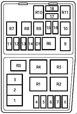
In the engine compartment
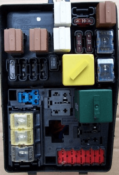
Located on the left side, near the battery, under the protective cover.
| Diagram | |
|---|---|
|
|
| № | Scheme designation |
| 1 | 80A Main supply on-board network electrical circuit |
| 2 | 60A Radiator fan motor |
| 3 | 60А ABS / TCS - system and under certain conditions diesel engine |
| 4 | 20A Ignition |
| 5 | 30A Heated windshield (left side) |
| 6 | 30A Heated windshield (right side) |
| 7 | 30A Braking system with ABS (anti-lock braking system) |
| 8 | 30A Heated seats, A / C compressor |
| 9 | 20A EEC module, cold start solenoid valve (diesel) |
| 10 | 20A Ignition lock |
| 11 | 3A EEC ignition module memory, Engine control unit |
| 12 | 15A Sound signal and light alarm |
| 13 | 15A Lambda Sensor |
| 14 | 15A Electric fuel pump (carburetor engine) |
| 15 | 10A Low beam right |
| 16 | 10A Low beam left |
| 17 | 10A High beam right |
| 18 | 10A High beam left |
| R1 | Daytime running light relay |
| R2 | Cooling fan relay (high speed) |
| R3 | Air conditioner relay |
| R4 | A / C clutch relay |
| R5 | Cooling fan relay (low speed) |
| R6 | Starter relay |
| R7 | Horn relay |
| R8 | Fuel pump relay |
| R9 | Low beam relay |
| R10 | High beam relay |
| R11 | Main relay |
| D1 | Reverse current protection diode |
View and print PDF:
