The 2nd generation Ford Mondeo compact car was produced in 1996, 1997, 1998, 1999 and 2000. Analogs of this model were sold on the American market - Ford Contour and Mercury Mystique. In this article, we will present a description of the 2nd generation Ford Mondeo fuses and relays with block diagrams in which they are located and photo examples of block execution. Separately, we highlight the fuse responsible for the cigarette lighter.

This model has two main blocks with fuses and relays. One is located in the cabin, the other under the hood.
In the passenger compartment
It is located under the dashboard on the left side.
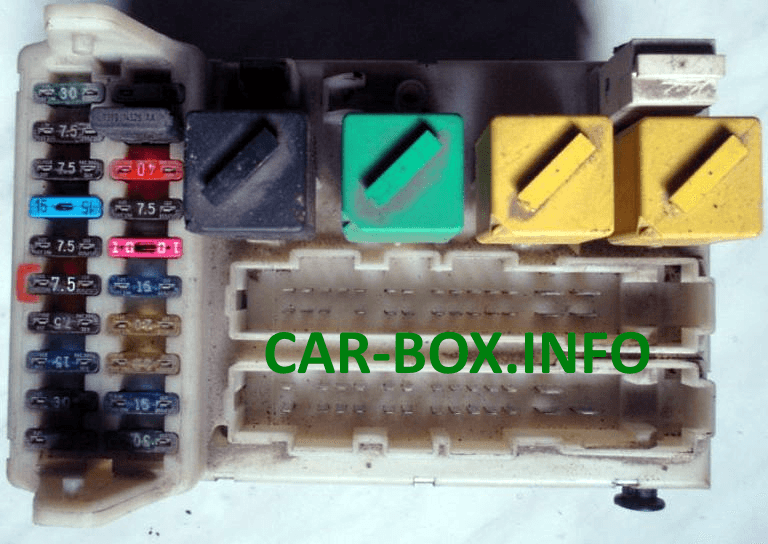
Photo - example.
| Diagram | |
|---|---|

|
|
| № | Purpose of fuses |
| 19 | 7,5A Electric door mirrors |
| 20 | 10A Windshield Wiper / Washer, Rear Window Washer Wiper |
| 21 | 30A / 40A Power windows, electric sunroof control unit |
| 22 | 7.5A ABS electronic control unit |
| 23 | 15A Direction indicators, active suspension system, cruise control, instrument cluster, gearbox control switch, lamp health control unit, windshield washer nozzle heaters, fuel filter heater relay |
| 24 | 15A Stop lights |
| 25 | 20A Central locking, anti-theft system, diagnostic socket |
| 26 | 20A Fog lights |
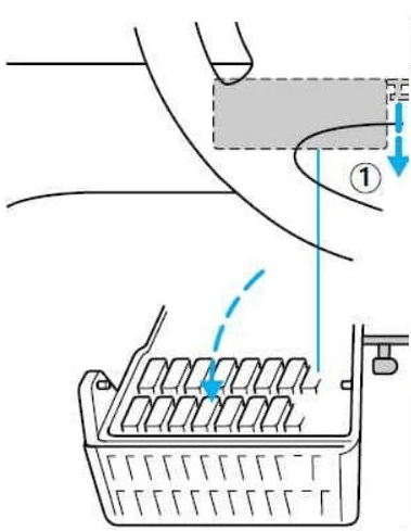
| 27 | 15A Cigarette lighter |
| 28 | 30A Relay for headlamp washer pump, power seat |
| 29 | 30A Heated rear window |
| 30 | 7.5A Engine management system, instrument cluster, auxiliary alarm unit, clock / trip computer |
| 31 | 7.5A Illumination of a combination of devices |
| 32 | 7,5А Audio system, Radio |
| 33 | 7,5A Front marker lamps - left |
| 34 | 7.5A Interior lamps, clock, power mirrors, tailgate / tailgate opening drive |
| 35 | 7,5A Front marker lamps - right |
| 36 | 15A / 30A Audio system, audio system output amplifier 10A Airbags |
| 37 | 30A Heater blower motor relay |
| 38 | 7,5A airbag |
| Fuse number 27 at 15A is responsible for the cigarette lighter. | |
|
|
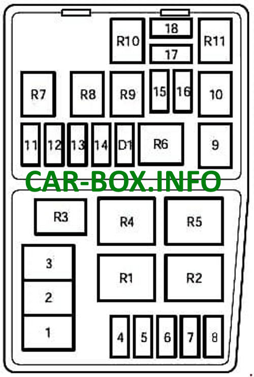
In the engine compartment
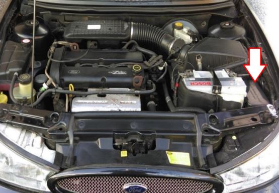
It is located on the left side, next to the battery. Several options for its execution are possible, and depends on the year of manufacture.
Type 1
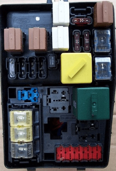
General view.
| Diagram | |
|---|---|
|
|
| № | Scheme designation |
| 1 | 80A Main supply on-board network electrical circuit |
| 2 | 60A Radiator fan motor |
| 3 | 60А ABS / TCS - system and under certain conditions diesel engine |
| 4 | 20A Ignition |
| 5 | 30A Heated windshield (left side) |
| 6 | 30A Heated windshield (right side) |
| 7 | 30A Braking system with ABS (anti-lock braking system) |
| 8 | 30A Heated seats, A / C compressor |
| 9 | 20A EEC module, cold start solenoid valve (diesel) |
| 10 | 20A Ignition lock |
| 11 | 3A EEC ignition module memory, Engine control unit |
| 12 | 15A Sound signal and light alarm |
| 13 | 15A Lambda Sensor |
| 14 | 15A Electric fuel pump (carburetor engine) |
| 15 | 10A Low beam right |
| 16 | 10A Low beam left |
| 17 | 10A High beam right |
| 18 | 10A High beam left |
| R1 | Daytime running light relay |
| R2 | Cooling fan relay (high speed) |
| R3 | Air conditioner relay |
| R4 | A / C clutch relay |
| R5 | Cooling fan relay (low speed) |
| R6 | Starter relay |
| R7 | Horn relay |
| R8 | Fuel pump relay |
| R9 | Low beam relay |
| R10 | High beam relay |
| R11 | Main relay |
| D1 | Reverse current protection diode |
Type 2

General view.
| Diagram | |
|---|---|

|
|
| № | Description |
| 1 | Fuel pump relay |
| 2 | Engine management system relay (petrol) |
| 3 | Full Throttle Position Relay (With A / C) |
| 4 | Headlamp low beam relay |
| 5 | High beam relay |
| 6 | Horn relay |
| 7 | Starter relay |
| 8 | Cooling fan motor relay 2 |
| 9 | Cooling fan motor relay 1 |
| 10 | Windshield heater timer relay |
| 11 | Daytime lighting relay |
| F1 | - |
| F2 | Generator |
| F3 | (20A) Auxiliary heater (Diesel) |
| F4 | (15A) Engine management system (bi-fuel system) |
| F5 | (15A) Engine management system (bi-fuel system) |
| F6 | (3A) Immobilizer (Diesel), engine management system |
| F7 | (15A) Horn, direction indicators |
| F8 | (5A) Engine management system (Bi-fuel) |
| F9 | (15A) Fuel pump |
| F10 | Engine management |
| F11 | (20A) Daytime running light relay (Scandinavian countries), engine management system, fuel heater |
| F12 | - |
| F13 | (20A) Heated oxygen sensor |
| F14 | - |
| F15 | (7.5A) RH headlamp - low beam |
| F16 | (7.5A) LH headlamp - low beam |
| F17 | (7.5A) RH headlamp-high beam |
| F18 | (7.5A) LH headlamp-high beam, instrument cluster |
| F39 | (60A) Glow plug relay |
| F40 | (20A) Ignition switch, light switch (headlights / fog lamps) |
| F41 | (20A) Engine management |
| F42 | (40A) Air conditioner / heater blower motor |
| F43 | - |
| F44 | - |
| F45 | (60A) Ignition main circuit relay |
| F46 | (30A) Heated windscreen (right side) |
| F47 | (30A) Heated windscreen (left side) |
| F48 | - |
| F49 | (60A) Cooling fan motors |
| F50 | - |
| F51 | (60A) ABS |
| F52 | (60A) Relay fuse box - instrument cluster 25, 27, 28, 36, windshield heater relay, lamp relay interior lighting |
