The 7th generation Ford Transit was produced in 2006, 2007, 2008, 2009, 2010, 2011, 2012 and 2013.
This model has received a major upgrade over previous models. In our article you will find a description of the Ford Transit 7 fuse blocks and relays, their diagrams and photographs. The fuse responsible for the “Cigarette lighter” is highlighted in bold.

General arrangement

The places where the blocks with fuses and relays are located: A - Additional fuse box, B - Fuse and relay box, C - Main fuse box, D - Hood fuse box
In the passenger compartment
Fuse box #1
It is located behind the glove compartment, so to get to it you need to remove the glove compartment itself and remove the protective cover of the unit. On the reverse side of which the current scheme will be applied.
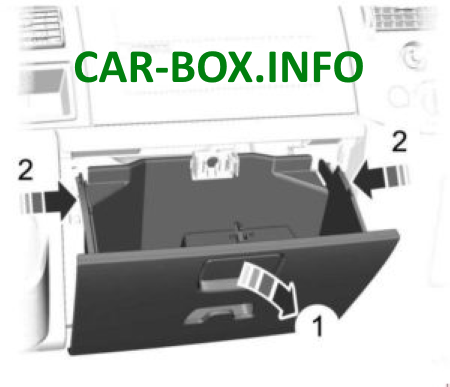
Location
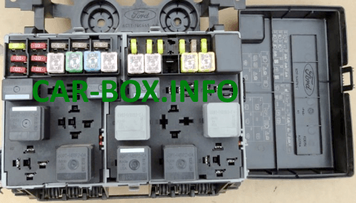
Photo - example
| Diagram | |
|---|---|
|
|
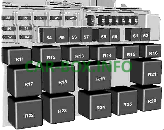
| № | Description |
| 38 | 20A Rear window cleaner |
| 39 | 10A Front and rear air conditioning controls |
| 40 | 5A Not used |
| 41 | 5A Tachograph |
| 42 | 5A Light beam leveling system, main switch (KL15) |
| 43 | 20A Heated front seats |
| 44 | 20A Buzzer |
| 45 | 20A Front auxiliary power socket |
| 46 | 10A Heated side mirrors, if CAT 1 is installed |
| 47 | 20A Cigarette lighter |
| 48 | 5A Power supply for relay coils, electric mirrors |
| 49 | 20A Rear auxiliary power socket |
| 50 | 10A High beam headlights. left-hand side |
| 51 | 10A High beam headlights. Right side |
| 52 | 10A Low beam headlights (left side) |
| 53 | 10A Low beam headlights. Right side |
| 54 | 30A Fuse for dipped and main beam headlights. daytime driving lights, tachograph and auxiliary fuel heater fan |
| 55 | 40A Heater fan motor |
| 56 | 20A Power windows |
| 57 | 30A Rear heater fan motor |
| 58 | 30A Front wiper motor |
| 59 | 30A Heated rear window and rear-view mirrors |
| 60 | Reserve |
| 61 | 60A Ignition relay (KL5 # 1) |
| 62 | 60A Ignition relay (KL5 # 2) |
| Relay | |
| R11 | Low beam headlamp switching circuit |
| R12 | Heated exterior mirrors (if equipped with a CAT 1 alarm). power socket (if CAT 1 alarm is not installed) |
| R13 | Headlights - high beam |
| R14 | Sound signal |
| R15 | Backlight when driving in daylight |
| R16 | Programmable fuel heater |
| R17 | Heated rear windows or rear-view mirrors (or heated the right side of the rear window if the CAT 1 alarm is installed) |
| R18 | Heated rear window (right side) if CAT 1 alarm is installed |
| R19 | Forced feed (KL15 # 2) |
| R20 | Electric junction box, passenger side KL15 (only vehicles with engine start / stop system) |
| R21 | Forced feed (KL15 # 1) |
| R22 | Heated windscreen, right side |
| R23 | Screen wiper (high and low cleaning speed) |
| R24 | Rear window wiper |
| R25 | Windshield wiper (on and off) |
| R26 | Heated windscreen, left side |
| The fuse number 47, 20A, is responsible for the Ford Transit cigarette lighter. | |
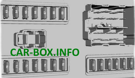
Fuse box #2
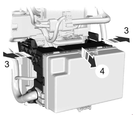
Located behind the fuse and relay box. In order to find it, you need to press to the sides on the 2 latches on the sides.

Execution example
| Diagram | |
|---|---|
|
|
| № | Appointment |
| 63 | 5A Reverse parking aid, rain sensor |
| 64 | 2A Accelerator pedal position sensor |
| 65 | 15A Brake light switch |
| 66 | 5A Instrument panel, power supply of the PATS security system, tachograph, control panel backlight |
| 67 | 15A Washer pump |
| 68 | 10A Restraint systems control unit |
| 69 | 20A External lighting switch (KL15) |
| 70 | 20A Sonar with emergency power supply |
| 71 | 5A External lighting switch (KL30) |
| 72 | 10A Power supply for the battery power consumption regulator. OBDII (KL30) |
| 73 | 15A Power supply for audio and navigation systems and mobile phone |
| 74 | 5A Instrument panel, auxiliary heater timer, power supply for the vehicle landing system without a key, motion sensor in the cabin (K1_30) |
| 75 | 7.5A Side lights on the right side |
| 76 | 7.5A Side lights on the left side |
| 77 | 5A Power supply to the ignition switch, power supply of the coils of the battery disconnect sensors |
| 78 | 15A Centralized locking system |
| 79 | 7.5A License plate lamp, side marker lights |
| 80 | 15A Front fog lamps |
| 81 | 10A Rear fog lamps |
| 82 | 3A Standard power supply of the audio unit and the instrument panel |
| Several fuses can be located separately: 83 - 10A - The towed trailer control module is located in the footwell on the left side 84 - 7.5A - DPF - control of the heating plugs is located in the electrical box located under the engine compartment |
|
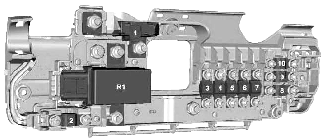
Power fuse panel
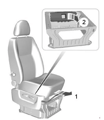
It is located behind the back of the driver's seat, under a protective cover. For access, the seat must be pushed back.
| Diagram | |
|---|---|
|
|
| № | Designation |
| 1 | 350A Starter and alternator |
| 2 | 60A Passenger side electrical junction box power supply to start the engine. Passenger side electro junction box for engine start / stop system |
| 3 | 100A Power supply to the junction box in the engine compartment (not important for starting) |
| 4 | 40A Heated windshield, right side |
| 5 | 100A Power supply to standard relay box (not important for starting) |
| 6 | 40A Heated windshield, left side |
| 7 | 60A Power supply to the junction box in the passenger compartment (not important for starting) |
| 8 | 60A Custom Connector |
| 9 | 60A Custom Connector |
| 10 | 60A Custom Connector |
| R1 | Secondary battery switch |
In engine compartment
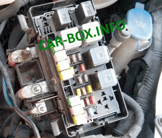
Located on the left side under the protective cover.
| Diagram | |
|---|---|

|
|
| № | Description |
| 11 | 60A Engine cooling fan motor |
| 12 | 30A Power supply circuits of the trailer hitch and trailer hitch unit (KL30) |
| 13 | 40A ABS and ESP pump |
| 14 | Reserve |
| 15 | 60A Glow plugs |
| 16 | 60A Ignition relay (KL15 # 3) |
| 17 | 30A Starter activation |
| 18 |
40A Between the power supply circuit of the ignition system (KL15) and the electrical junction box, passenger side (vehicles without engine start / stop system) |
| Reserve (vehicles with engine start / stop system) | |
| 19 | Reserve |
| 20 | 10A ABS power supply. ESP. steering shaft position sensor and yaw rate sensor (YAW) (KL30) |
| 21 | 25A Valves and control unit ABS and ESP |
| 22 | Reserve |
| 23 | Reserve |
| 24 | 5A Fuel pump (vehicles without auxiliary heater, fuel fired) |
| 24 | 20A Fuel pump (vehicles with fuel fired auxiliary heater) |
| 25 | Reserve |
| 26 | 15A PCM Power Relay |
| 27 | 5A Fuel pump (vehicles with fuel fired auxiliary heater) |
| 28 | 5A Combined temperature and mass air flow (T-MAF) sensor |
| 29 | 5A Evaporator Glow Plug Monitoring |
| 30 | 7.5A Sonic purge valve |
| 31 | 15A YAP / UEGO pump |
| 32 | 20A Evaporator glow plug |
| 33 | 10A Reversing lights |
| 34 | 20A Trailer power supply KL15 |
| 35 | Reserve |
| 36 | 10A Air conditioning compressor clutch |
| 37 | Reserve |
| Relay | |
| R2 | Glow plugs |
| R3 | Towing a trailer (KL15) |
| R4 | Starter activation |
| R5 | Forced feed (KL15 # 4) |
| R6 | Forced feed (KL15 # 3) |
| R7 | Fuel pump |
| R8 | Evaporator Glow Plug |
| R9 | Not used |
| R10 | Air conditioning compressor clutch solenoid |
