The 3rd generation Ford Galaxy has been assembled since 2014. Years 2015, 2016, 2017, 2018, 2019, 2020, 2021 and up to now. In this publication, we will show the location of the blocks and a description of the fuses and relays of the 3rd generation Ford Galaxy, with diagrams and their photographs. Note the fuses responsible for the cigarette lighter.

The actual assignment of fuses and relays may differ from the one presented and depends on the year of manufacture and the level of electrical equipment of your car.
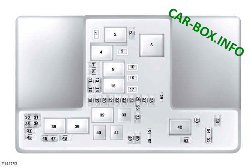
In the passenger compartment
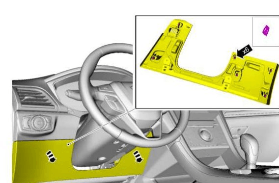
It is located on the left side of the dashboard and is combined with the BCM (body conrol module). For comfortable access, part of the protection must be removed.

Photo example
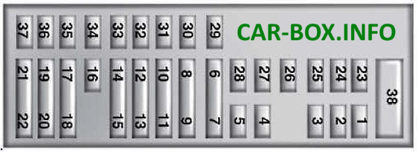
| Diagram | |
|---|---|
|
|
| № | Description |
| 1 | 10A Background lighting, Glove box lamp, Vanity mirror lamp, Ceiling lamp, Luggage compartment lamp |
| 2 | 7.5A Seat with memory function, Lower backrest support, driver's seat, Power mirrors |
| 3 | 20A Unlock driver's door |
| 4 | 5A Electronic trailer brake |
| 5 | 20A Ignition switch, Start button |
| 6 | 10A Heated seats |
| 7 | 10A Reserve |
| 8 | 10A Reserve |
| 9 | 10A Reserve |
| 10 | 5A Power tailgate module |
| 11 | 5A Reserve |
| 12 | 7.5A Integrated module for front controls (climate control system and radio receiver) |
| 13 | 7.5A Steering column, Instrument panel, Diagnostic connector |
| 14 | 10A Reserve |
| 15 | 10A Data link gateway |
| 16 | 15A Childproof lock, Luggage lift window unlock |
| 17 | 5A Reserve |
| 18 | 5A Ignition lock (switch), Ignition switch with a push button |
| 19 | 7.5A Passenger airbag deactivation indicator, Gear range indicator |
| 20 | 7.5A Reserve |
| 21 | 5A Humidity and temperature sensor in the car, Control systems "blind / dead" zones, Rear camera, Adaptive cruise control system |
| 22 | 5A Passenger classification sensor |
| 23 | 10A Auxiliary equipment off delay power supply circuit |
| 24 | 20A Lock / Unlock |
| 25 | 30A Driver's door window, Driver's door mirror |
| 26 | 30A Front passenger door window, Front passenger door mirror |
| 27 | 30A Sunroof |
| 28 | 20A Amplifier |
| 29 | 30A Rear door window, driver's side |
| 30 | 30A Rear door window, passenger side |
| 31 | 15A Reserve |
| 32 | 10A Global Positioning System Module, Voice Control (SYNC), Infotainment Display, RF Radio, Adaptive Cruise Control |
| 33 | 20A Radio |
| 34 | 30А Bus "start / run" (fuse 19, 20, 21, 22, 35, 36, 37, circuit breaker) |
| 35 | 5A Airbag and seat belt control module |
| 36 | 15A Auto-dimming interior mirror, Heated rear seat module, AWD system |
| 37 | 15A Voltage stabilization module |
| 38 | 30A Not used |
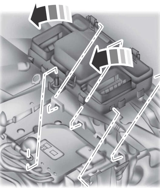
In the engine compartment
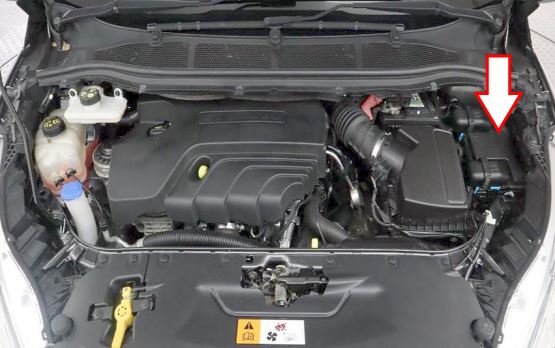
It consists of 2 sections and is located on the left side, next to the stand and is closed with a protective cover.
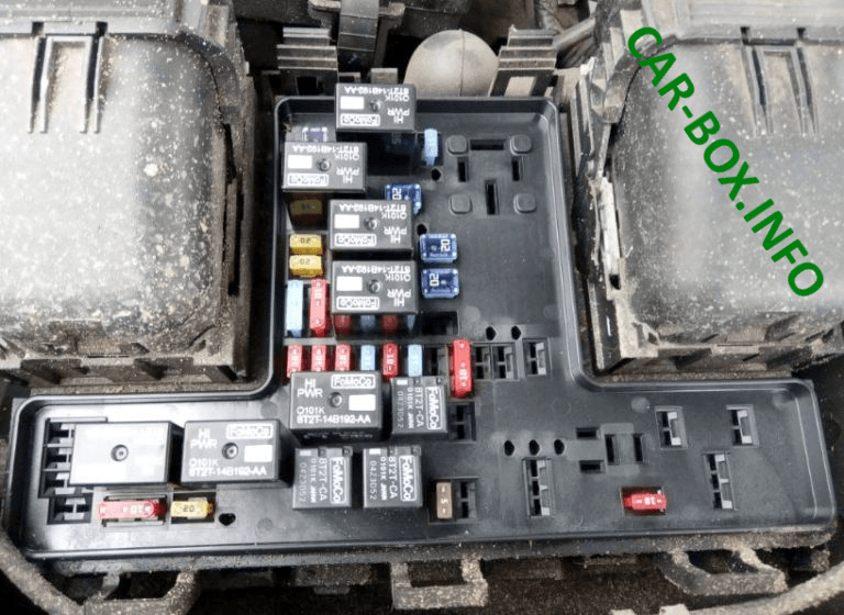
| Diagram and photo (upper section) | |
|---|---|
|
|
|
|
| № | Description |
| 1 | 25A Windshield wiper 30A Hatch |
| 2 | Starter relay |
| 3 | 15A Automatic operation glass wipers, rain sensor, rear wipers |
| 4 | Relay for electric blower fan |
| 5 | 20A Accessory power outlet on the back of the console |
| 6 | Auxiliary heater relay |
| 7 | 20A Powertrain control module |
| 8 | 20A Powertrain control module |
| 9 | Powertrain control module relay |
| 10 | 20A Front auxiliary power sockets, driver's side |
| 11 | 15A Powertrain control module |
| 12 | 15A Powertrain control module |
| 13 | 10A Powertrain control module |
| 14 | 10A Powertrain control module |
| 15 | Run / Start Relay |
| 16 | 20A Auxiliary power outlet on console, cigarette lighter |
| 17 | 20A Additional power socket in the luggage compartment |
| 18 | 10A Powertrain control module |
| 19 | 10A Power steering |
| 20 | 10A Illumination of the "start / stop" position, cruise control |
| 21 | 15A Transmission control module, transmission oil pump |
| 22 | 10A Air conditioning system |
| 23 | 15A. Start / stop, blind spot information system, rear view camera, adaptive cruise control, proximity warning, voltage quality module, air quality sensor |
| 24 | 10A Reserve |
| 25 | 10A Anti lock brake system, ABS |
| 26 | 10A Powertrain control module. |
| 27 | 10A Reserve |
| 28 | 10A Rear window washer pump. |
| 29 | 5A Air mass meter |
| 30 | Reserve |
| 31 | Reserve |
| 32 | Cooling fan relay |
| 33 | Air conditioning relay |
| 34 | 15A Electric steering column lock. |
| 35 | Reserve |
| 36 | Reserve |
| 37 | Reserve |
| 38 | Cooling fan relay |
| 39 | Cooling fan relay |
| 40 | Horn relay |
| 41 | Horn relay |
| 42 | Fuel pump relay |
| 43 | Rezrv |
| 44 | 5A Heated washer spray |
| 45 | Reserve |
| 46 | 10A Generator |
| 47 | 10A Brake Switch |
| 48 | 20A Buzzer |
| 49 | 5A Air flow sensor 20A Heating element for diesel fuel |
| 50 | 10A Cooling fan, transfer case 20A Signal |
| 51 | Reserve |
| 52 | Reserve |
| 53 | 10A Power seats. |
| 54 | 5A Remote control for fuel-fired heater, 10A Brake switch |
| 55 | 10A ALT sensor |
| For the operation of Ford Galaxy cigarette lighters and USB sockets, fuses 17, 16, 10 and 5 at 20A are responsible. | |
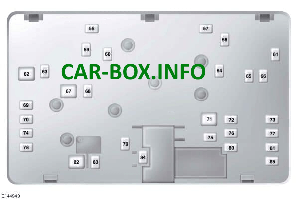
| Access example and diagram (lower section) | |
|---|---|
|
|
|
|
| № | Appointment |
| 56 | 30A Fuel pump |
| 57 | 20A Diesel fuel vaporizer |
| 58 | Reserve |
| 59 | 30 / 40A Cooling Fan (DW10F and 2.0L GTDI AU) |
| 60 | 30 / 40A Cooling Fan (DW10F and 2.0L GTDI AU) |
| 61 | 40A Heated windshield (left side) |
| 62 | 50A Body systems control unit |
| 63 | 20 / 30A Cooling Fan (DW10F and 2.0L GTDI AU) |
| 64 | 30A Additional heater |
| 65 | 20A. Heated front seats |
| 66 | 40A Heated windshield (right side) |
| 67 | 50A Body systems control unit |
| 68 | 40A Heated rear window |
| 69 | 30A Anti lock brake system |
| 70 | 30A Passenger seat |
| 71 | 60A Additional heater |
| 72 | 20A Fuel pump 30A Sunroof or Rear seats |
| 73 | 20A Rear heated seat |
| 74 | 30A Driver's seat module |
| 75 | 30A Additional heater |
| 76 | 20A transmission oil pump |
| 77 | 30A Climate-controlled seat module |
| 78 | 40A Trailer towing module |
| 79 | 40A Electro blower fan. |
| 80 | 30A Power module in the luggage compartment. |
| 81 | 40A Inverter 220 V. |
| 82 | 60A Anti-lock brake system pump. |
| 83 | 25A Cleaner motor |
| 84 | 30A Starter solenoid. |
| 85 | 20A Fuel-fired heater 60A Anti-lock brake pump |
If you have any questions or want to help supplement the material, write in the comments.
