
The second-generation Focus compact car was produced from 2004 through 2011 with both gasoline and diesel engines. During this production run, the model received a facelift, updating both the interior and exterior design. This publication provides descriptions, locations, circuit diagrams, and photographs for the Ford Focus Mk2 (C1 platform; chassis code C307) fuse and relay boxes. The fuse for the cigarette lighter is highlighted in bold.
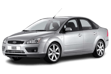
Actual fuse assignments and ratings may vary depending on the model year, trim level, and market destination for the Ford Focus Mk2. Always verify circuit designations against the diagram on the back of the fuse box cover.
General Arrangement
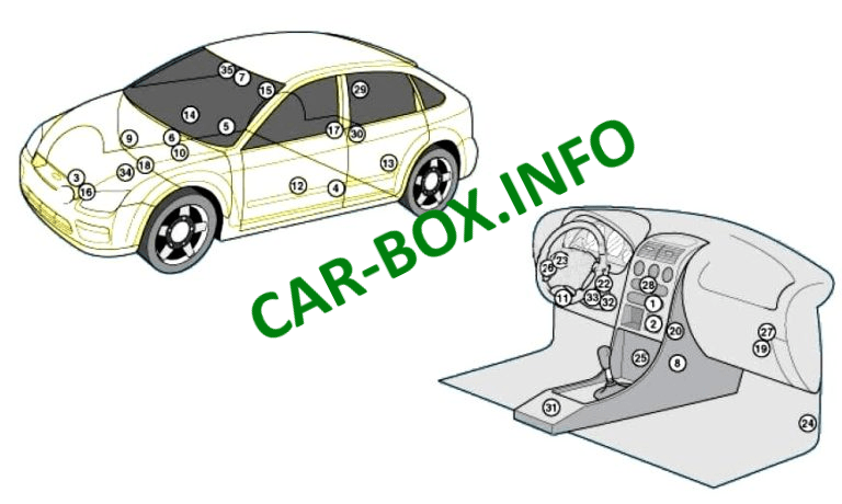
Locations of all electronic control units (ECUs) and electrical modules.
|
|
| № | Description |
| 1 | Air conditioning electronic control unit (A/C ECU) |
| 2 | Ambient air temperature sensor (dashboard ventilation grille) |
| 3 | Supplemental Restraint System (SRS) impact sensor |
| 4 | Driver-side SRS side-impact sensor |
| 5 | Passenger-side SRS side-impact sensor |
| 6 | Anti-theft alarm siren / sounder |
| 7 | Sunlight / Solar sensor |
| 8 | Auxiliary electric heater |
| 9 | Auxiliary fuel-fired heater |
| 10 | Battery |
| 11 | Diagnostic Link Connector (DLC / OBD-II) |
| 12 | Driver door control module (in door panel) |
| 13 | Left rear door control module (in door panel) |
| 14 | Front passenger door control module (in door panel) |
| 15 | Right rear door control module (in door panel) |
| 16 | Engine cooling fan control module |
| 17 | Fuel additive control module (DPF) |
| 18 | Engine compartment fuse and relay box (BJB) |
| 19 | Passenger compartment fuse and relay box (CJB) |
| 20 | Blower motor resistor (adjacent to blower motor) |
| 21 | Horn |
| 22 | Passive Anti-Theft System (PATS) transceiver ring antenna |
| 23 | Turn signal flasher relay (integrated into turn signal switch) |
| 24 | Inertia fuel shut-off switch |
| 25 | Keyless entry control module |
| 26 | Lighting control switch / module |
| 27 | Generic Electronic Module (GEM) / Passenger compartment fuse box – Controls: Air conditioning, anti-theft system, auxiliary electric heater, central locking, heated windshield, interior lamps, windshield wiper/washer system |
| 28 | Navigation control module |
| 29 | Parking aid control module (PDC) |
| 30 | Electronic parking brake (EPB) control module |
| 31 | SRS / Airbag control module |
| 32 | Steering column lock module |
| 33 | Steering angle sensor |
| 34 | Transmission Control Module (TCM) |
| 35 | Rain sensor (windshield wipers) |
Engine Compartment Fuse Box

Located on the left side of the engine bay beneath the protective cover.
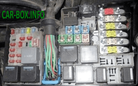
Overview photograph.

Sample circuit diagram printed on the inside of the protective cover.
| Diagram | |
|---|---|

|
|
| № | Description |
| F1 | 40 A / 60 A: Engine cooling fan motor |
| F2 | 80 A: Electro-hydraulic power steering (EHPAS) |
| F3 | 60 A :Passenger compartment fuse box power feed |
| F4 | 60 A: Passenger compartment fuse box power feed |
| F5 | 80 A: Climate control system (manual or automatic) |
| F6 | 60 A: Spare |
| F7 | 30 A: ABS hydraulic pump unit |
| F8 | 20 A: ABS hydraulic unit valves |
| F9 | 20 A: Main powertrain relay contacts and coil |
| F10 | 30 A: Blower motor |
| F11 | 20 A: Ignition switch |
| F12 | 40 A: Ignition relay power supply |
| F13 | 20 A: Starter motor solenoid |
| F14 | 40 A: Heated windshield (right element) |
| F15 | 30 A: Cooling fan relay |
| F16 | 40 A: Heated windshield (left element) |
| F17 | 30 A: Spare |
| F18 | Spare |
| F19 | 10 A: ABS control module |
| F20 | 15 A: Horn |
| F21 | 20 A: Auxiliary heater |
| F22 | 10 A: Power steering control module (EHPAS) |
| F23 | 30 A: Headlamp washer pump |
| F24 | 15 A: Spare |
| F25 | 10 A: Heated windshield relay coil |
| F26 | 10 A: Automatic transmission control module (TCM) |
| F27 | 10 A: A/C compressor clutch |
| F28 | 10 A: Spare |
| F29 | 10 A: Dual-zone automatic climate control system (EATC) |
| F30 | 3 A: Powertrain Control Module (PCM), Transmission Control Module (TCM) |
| F31 | 10 A: Alternator / Battery charging system |
| F32 | 10 A: Transmission Control Module (TCM), gear selector position sensor |
| F33 | 10 A: Heated oxygen sensors (HO2S) |
| F34 | 10 A: Fuel injectors, ignition coil |
| F35 | 10 A: Engine management system |
| F36 | 10 A: Powertrain Control Module (PCM) |
| Relay Assignments | |
| R1 | Starter inhibit relay |
| R2 | Horn relay |
| R3 | Reversing light relay |
| R4 | Spare |
| R5 | Exhaust Gas Recirculation (EGR) relay (gasoline) / Fuel heater relay (diesel) |
| R6 | Main powertrain relay |
| R7 | Heated windshield relay |
| R8 | Ignition relay |
| R9 | Headlamp washer relay |
| R10 | Blower motor relay |
| R11 | A/C compressor clutch relay |
| R12 | Radiator cooling fan relay / Glow plug relay |
| R13 | Starter motor relay |
| R14 | Radiator cooling fan relay |
Passenger Compartment Fuse Box
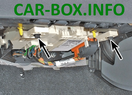
Located beneath the glove compartment and secured with two retaining screws.
Type 1
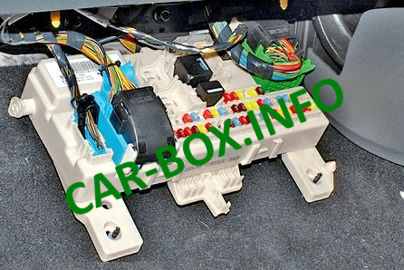
Overview.
| Diagram | |
|---|---|
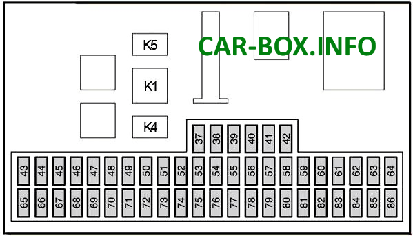
Circuit diagram |
|
| № | Description |
| 37 | 10 A: Left high-beam headlamp |
| 38 | 10 A: Right high-beam headlamp |
| 39 | 20 A: Cigarette lighter, rear auxiliary power socket |
| 40 | 20 A: Power sunroof |
| 41 | 20 A: Front passenger door module |
| 42 | 7.5 A: Heated exterior mirrors |
| 43 | 10 A: Electronic modules (battery power supply) |
| 44 | 10 A: Diagnostic Link Connector (OBD-II / DLC) |
| 45 | 10 A: Daytime running lights (DRL) |
| 46 | 10 A: Instrument cluster, Generic Electronic Module (GEM) |
| 47 | 15 A: Windshield washer pump, heated washer jets |
| 48 | 20 A: Low-beam headlamps, daytime running lights (DRL) |
| 49 | 15 A: Light switch |
| 50 | 20 A: Front windshield wipers |
| 51 | 15 A: Fuel pump |
| 52 | 25 A: Heated rear window |
| 53 | 7.5 A: Left side / position lights |
| 54 | 7.5 A: Right side / position lights |
| 55 | 20 A: Driver door module, central locking system |
| 56 | 20 A: Keyless Entry / Start system |
| 57 | 10 A: Anti-theft system alarm siren |
| 58 | 15 A: Audio system (battery power supply) |
| 59 | 25 A: Luggage compartment power socket, trailer socket |
| 60 | 15 A: Right low-beam headlamp |
| 61 | 15 A: Left low-beam headlamp |
| 62 | 20 A: Power driver seat adjustment |
| 63 | 25 A: Power windows |
| 64 | Spare |
| 65 | 10 A: Supplemental Restraint System (Airbags) |
| 66 | 7.5 A: Headlamp levelling control, low-beam headlamps, Xenon headlamp module |
| 67 | 10 A: Immobilizer (PATS), instrument cluster (ignition power supply) |
| 68 | 7.5 A: Audio system, instrument cluster |
| 69 | 20 A: Front fog lights |
| 70 | 10 A: Electronic modules (ignition power supply) |
| 71 | 10 A: Daytime running lights (DRL) |
| 72 | 25 A: Generic Electronic Module (GEM) |
| 73 | 7.5 A: License plate lights |
| 74 | 15 A: Brake lights |
| 75 | 10 A: Transmission Control Module (TCM), electronic accelerator pedal |
| 76 | 7.5 A: Electronic Parking Brake (EPB) |
| 77 | 25 A: Central locking relay |
| 78 | 15 A: Rear window wiper |
| 79 | 15 A: Power folding mirrors |
| 80 | 10 A: Interior lamps, power exterior mirrors |
| 81 | 20 A: Right rear door module |
| 82 | 20 A: Left rear door module |
| 83 | 10 A: CD changer, Rear Seat Entertainment (RSE) |
| 84 | 10 A: Reversing lights, trailer module |
| 85 | 10 A: Cooling fan system |
| 86 | 20 A: Heated seats |
| In this configuration, Fuse 39 (20 A) powers the Ford Focus cigarette lighter socket. | |
| Relay Assignments | |
| K1 | Heated rear window relay |
| K4 | Fuel pump relay |
| K5 | Daytime running lights (DRL) relay |
Type 2
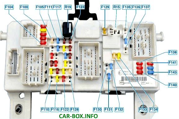
Circuit diagram.
| № | Description |
| 100 | 10 A: Electronic modules (ignition power supply) |
| 101 | 20 A: Power sunroof, power driver seat, retractable hardtop control module (Focus Coupe-Cabriolet) |
| 102 | 10 A: Climate control module, power steering column adjustment, Diesel Particulate Filter (DPF), remote control receiver |
| 103 | 10 A: Exterior lighting switch (battery power supply) |
| 104 | 10 A: Interior lamps, battery saver system |
| 105 | 25 A: Heated rear window |
| 106 | 20 A: Keyless Entry / Start system |
| 107 | 10 A: Instrument cluster (battery power supply), Diagnostic Link Connector (DLC) |
| 108 | 7.5 A: Instrument cluster auxiliary display functions (audio and navigation) |
| 109 | 20 A: Cigarette lighter, rear auxiliary power socket |
| 110 | 10 A: Daytime running lights (DRL) switch |
| 111 | 15 A: Fuel pump (gasoline engines) |
| 112 | 15 A: Audio system (battery power supply) |
| 113 | 10 A: Daytime running lights (DRL) |
| 114 | 10 A: Instrument cluster (ignition power supply), immobilizer (PATS) |
| 115 | 7.5 A: Exterior lighting switch (ignition power supply) |
| 116 | 20 A: Front fog lights |
| 117 | 7.5 A: License plate lights |
| 118 | 20 A: Left rear door module |
| 119 | 15 A: Luggage compartment power socket |
| 120 | 20 A: Right rear door module |
| 121 | 20 A: Heated front seats |
| 122 | 10 A: Supplemental Restraint System (Airbags) |
| 123 | 7.5 A: Heated exterior mirrors |
| 124 | 7.5 A: Left side / position lights |
| 125 | 7.5 A: Right side / position lights |
| 126 | 20 A: Keyless Entry / Start system |
| 127 | 25 A: Power windows |
| 128 | Spare |
| 129 | 20 A: Front windshield wipers |
| 130 | Spare |
| 131 | 15 A: Rear window wiper |
| 132 | 15 A: Brake lights |
| 133 | 25 A: Front passenger door module, central locking relay |
| 134 | 20 A: Driver door module, central locking system |
| 135 | 20 A: Daytime running lights (DRL) |
| 136 | 15 A :Windshield washer pump, heated washer jets |
| 137 | 10 A: Anti-theft system backup power supply (battery-backed siren) |
| 138 | 10 A: Powertrain Control Module (PCM), electronic accelerator pedal, Transmission Control Module (TCM) |
| 139 | 10 A: Right high-beam headlamp |
| 140 | 10 A: Left high-beam headlamp |
| 141 | 10 A: Reversing lights, power exterior mirrors |
| 142 | 15 A: Right low-beam headlamp |
| 143 | 15 A: Left low-beam headlamp |
| R1 | Fuel pump relay |
| R2 | Spare |
| Fuse 109 (20 A) powers the cigarette lighter socket. | |
Individual relays may be located on the rear side of the junction box.
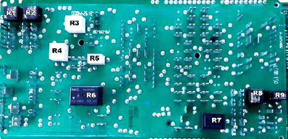
Relay Assignments
- R1 Low-beam headlamp relay
- R2 High-beam headlamp relay
- R3 Central locking and rear wiper relay
- R4 Driver door unlock relay
- R5 Passenger doors unlock relay
- R6 Front windshield wiper relay
- R7 Heated rear window relay
- R8 Battery saver relay
- R9 Exterior lighting relay

Thank you for my patience who trusted me so that no one would know about it