The new version of the Honda CR-V, like the previous generations of this model, has undergone dramatic changes. Apart from the new body, which has become more rigid in torsion and bending, the engines and suspension have undergone significant modernization, as well as the all-wheel drive system. In this material, we will analyze in detail the 4th generation Honda CR-V fuse circuits (RE; RM) 2012, 2013, 2014, 2015, 2016, 2017, 2018 release.

Here you will find the locations and photos of the fuse distribution boxes. The fuses responsible for the “Cigarette lighter” and “Fuel Pump” are highlighted in bold.
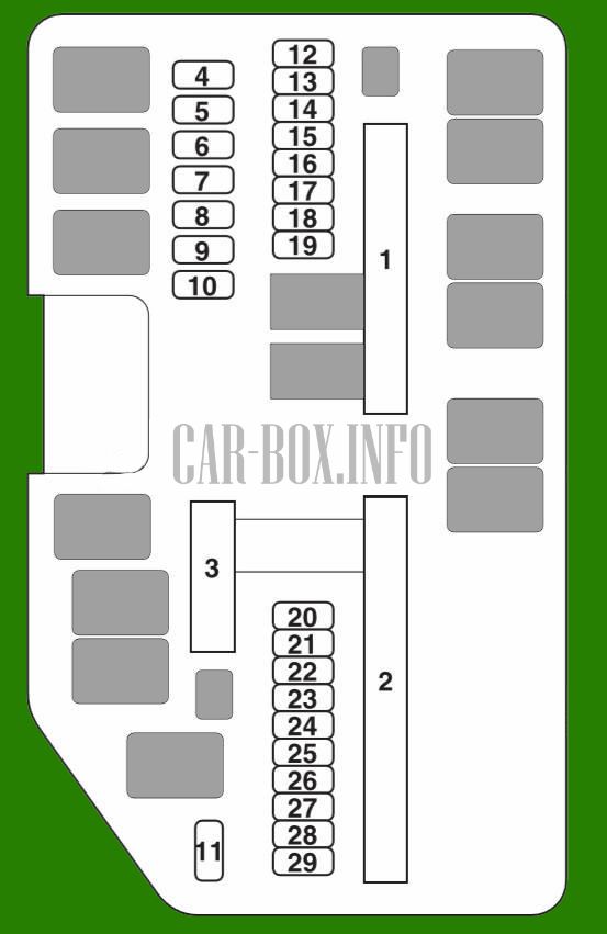
In the passenger compartment
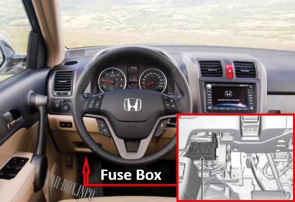
Located at the bottom of the dashboard.
The photo shows an example.
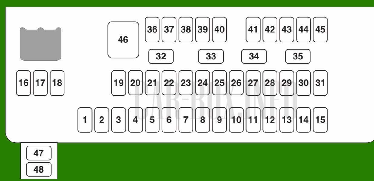
| Diagram | ||
|---|---|---|
|
||
| No. | A | Description |
| 1 | - | No |
| 2 | 10 | ACG |
| 3 | 10 | Airbag System (SRS) |
| 4 | 15 | Fuel pump fuse honda CR-V |
| 5 | 10 |
|
| 6 | 7.5 | Electric windows |
| 7 | 7.5 | VB SOL * |
| 8 | 15 | Passenger door lock gear motor (unlocking) |
| 9 | 10 | Motor gearbox of the passenger door lock behind the driver (unlocking) |
| 10 | 10 | Daytime Running Lights |
| 11 | 20 | A roof with a panoramic view* |
| 12 | 20 | Electrical outlet (center console compartment) |
| 13 | 15 | Washer * |
| 14 | 20 | Heated seats* |
| 15 | 10 | Driver's door lock gear motor (unlocking) |
| 16 | 20 | Electric longitudinal adjustment of the driver's seat * |
| 17 | 20 | Driver's electric backrest tilt function * |
| 18 | 20 | Electric tailgate closing * |
| 19 | 7.5 | ACC |
| 20 | 7.5 | Ignition key lock ACC |
| 21 | 7.5 | Daytime Running Lights |
| 22 | 7.5 | Air conditioner |
| 23 | 10 | Wiper / Washer Relay |
| 24 | 7.5 | ABS / VSA relay * 1 2 * 2 |
| 25 | 7.5 | Backup FL ECU I / S APD * 2 |
| 10 | Audio system * 1 | |
| 26 | 20 | Super locking of door locks * |
| 27 | 20 | Electrical outlet (front console), cigarette lighter fuse |
| 28 | 15 | Washer * |
| 29 | 7.5 | SRS2 |
| 30 | 10 | Driver's door lock gear motor (blocking) |
| 31 | 10 | Smart * |
| 32 | 15 | Motor gearbox of door locks on the front passenger side (blocking) |
| 33 | 15 | Driver's side door locks gear motor (blocking) |
| 34 | 10 | Low power lamps |
| 35 | 7.5 | Lighting |
| 36 | 10 | Rear wiper main fuse * |
| 37 | 15 | Turning headlight * |
| 38 | 10 | Left headlight (high beam) |
| 39 | 10 | Right headlight (high beam) |
| 40 | 7.5 | Rear fog lamp |
| 41 | 20 | Door locks |
| 42 | 20 | Driver's door window regulator |
| 43 | 20 | Power window rear right door |
| 44 | 20 | Front passenger door power window |
| 45 | 20 | Power window, rear left door |
| 46 | 20 | Starter* |
| 30 | Windshield wiper * | |
| 47 | 7.5 | UBECU * |
| 48 | No | |
| Note : * 1. Vehicles not equipped with an auto-idle system * 2: Vehicles equipped with an auto-idle system | ||
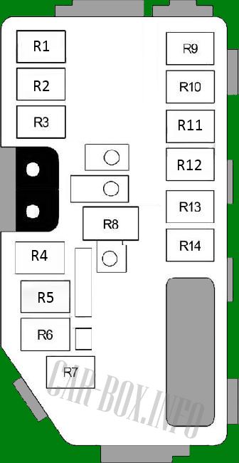
| Purpose of relay modules | ||

|
||
| R1 | Engine control unit (No. 2) | |
| R2 | Front outlet | |
| R3 | Starter relay | |
| R4 | Throttle body (ETCS) | |
| R5 | Engine control unit (No. 1) | |
| R6 | Power window relay | |
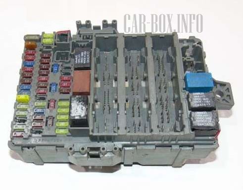
In the engine compartment
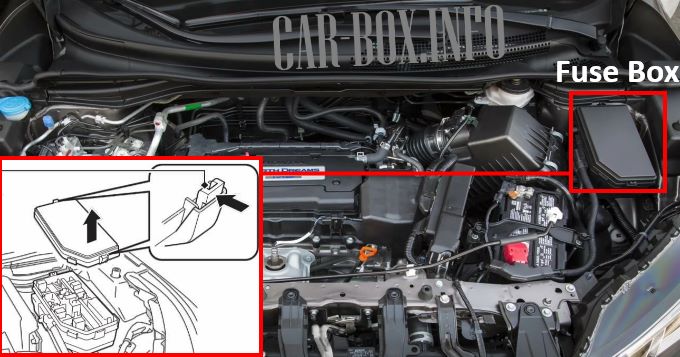
The fuse block is located on the left side of the engine compartment.
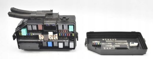
General view.
| Diagram | ||
|---|---|---|
|
||
| No. | A | Decoding |
| 1 | 70 | Electric power steering (EPS) |
| 30 | Left pretensioner *, * 1 | |
| 70 | Glow plugs * 2, * 3 | |
| 40 | ABS / VSA motor | |
| 20 30 |
|
|
| 30 | E-DPS * 1 | |
| 100 * 1 | Main fuse | |
| 150 * 2, * 3 | ||
| 2 | 50 | Ignition switch |
| 60 | Main unit fuse | |
| 60 | Main fuse for block 2 | |
| 30 | Main headlight fuse | |
| 30 |
|
|
| 30 | Relay ST * 1 | |
| 30 | Heated rear window * 1 | |
| 30 | Right e-pretensioner *, * 1 | |
| 30 | DC / DC 2 * 2, * 3 | |
| 40 | Ventilation fan motor | |
| 30 | Windshield wiper main fuse * 1 | |
| 30 | Heated rear window * 2, * 3 | |
| 20 * 1 | Auxiliary fan motor | |
| 20 * 1 | Main fan motor | |
| 3 | 40 | A / C PTC # 1,2,3,4: * 2, * 3 |
| 4 | - | No |
| 5 | - | No |
| 6 |
|
|
| 7 | 10 | Reversing lights * 2, * 3 |
| 8 | 7.5 | Sub Fan RLY CL * 1 |
| 9 | 7.5 |
|
| 10 | 7.5 | Interior lighting 3 Reversing light 2 * 2 |
| 11 | 7.5 |
|
| 12 | 20 | Fog lights* |
| 13 | 20 30 |
|
| 14 | 10 | Sound signal |
| 15 | 10 | Alarm |
| 16 | 10 A * 1 | Stop signal |
| 15 A * 2, * 3 | ||
| 17 | 15 | IG Coil * 1 |
| 10 | Laf * 2, * 3 | |
| 18 | 15 | IGP 2 |
| 19 | 20 | ABS / VSR FSR (Min) * 2, * 3 |
| 21 | 30 | Headlight washer* |
| 22 | 15 | Drive By Wire * 1 |
| 7.5 | Back Up FI ECU * 2, * 3 | |
| 23 | 15 * 1 | IGP |
| 20 * 2, * 3 | ||
| 24 | Left headlight (low beam) | |
| 25 | Right headlight (low beam) | |
| 26 | 20 | Side lights, main |
| 27 | 7.5 | Coupling MG |
| 7.5 | Interior lighting * 1 | |
| 28 | 20 | Standby, Interior lighting, main * 2, * 3 |
| 29 | 10 | Buck Up * 1 |
| 29 | 20 | Rear ACC * 2, * 3 |
|
||
| Description of relay modules | |
|
|
| R1 | Heater |
| R2 | - |
| R3 | Air conditioner fan |
| R4 | Ignition coils |
| R5 | Front fog light |
| R6 | Engine control unit (PGM-FI) |
| R7 | Heated rear window |
| R8 | Electrical Load Cell (ELD) |
| R9 | - |
| R10 | Sound signal |
| R11 | Fan control |
| R12 | Cooling fan |
| R13 | - |
| R14 | A / C Compressor Clutch |
