
Table of Contents
The CR-V is a compact crossover SUV manufactured by Honda since 1995. In this article, we will examine in detail the fuse box diagrams for the 6th-generation Honda CR-V (chassis codes RS / ZC; HA platform) for the 2022, 2023, 2024, 2025, 2026, and 2027 model years.

Here you will find the locations and photos of the fuse boxes. We will specifically highlight the fuses responsible for the cigarette lighter and fuel pump.
Interior
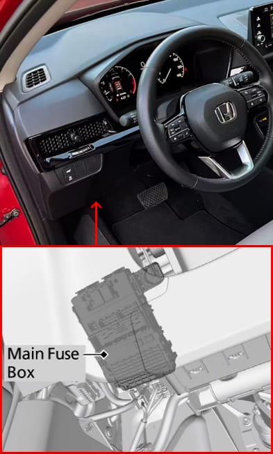
The fuse box is located on the driver's side, under the dashboard.
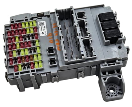
General view.
| Diagram | ||
|---|---|---|

|
||
| No. | Circuit Description | Current (A) |
| 1 | P/W DR — Driver's door power window | 20 A |
| 2 | P/W AS — Front passenger door power window | 20 A |
| 3 | P/W RR R — Right rear door power window | 20 A |
| 4 | P/W RR L — Left rear door power window | 20 A |
| 5 | OPTION — Optional equipment circuit | 10 A |
| 6 | SRS — Supplemental Restraint System (SRS) power | 10 A |
| 7 | T/G MTR / TRUNK ACT — Power tailgate motor / Trunk actuator | 10 A |
| 8 | RVU — Rearview camera / Surround view system module | 10 A |
| 9 | FR ACC SOCKET — Front accessory power socket (12V) / Cigarette lighter | 20 A |
| 10 | DOOR LOCK — Power door locks | 20 A |
| 11 | METER — Instrument cluster | 10 A |
| 12 | OPTION 3 (ST CUT) — Option circuit 3 / Starter cut relay | 10 A |
| 13 | OPTION 2 — Optional equipment 2 | 10 A |
| 14 | OPTION 6 (VB SOL) — VTEC/VTC system solenoid | 10 A |
| 15 | DR DOOR UNLOCK — Driver's door unlock circuit | 10 A |
| 16 | IMG — Immobilizer system module | 10 A |
| 17 | YOP TRAILER — Trailer control module / Trailer socket | 20 A |
| 18 | HAC OP — Hill Start Assist (HSA) system | 20 A |
| 19 | Spare | — |
| 20 | Spare | — |
| 21 | Spare | — |
| 22 | USB CHG — USB charging module power | 10 A |
| 23 | CARGO ACC SOCKET — Cargo area accessory power socket (12V) | 20 A |
| 24 | SMART — Smart Key system module | 10 A |
| 25 | DR DOOR LOCK — Driver's door lock circuit | 10 A |
| 26 | E-DPS — Electronic Dual Pump System (AWD) control unit | 20 A |
| 27 | Spare | — |
| 28 | Spare | — |
| 29 | Spare | — |
| 30 | SRS — Supplemental Restraint System secondary circuit | 10 A |
| 31 | ACG — Alternator Control circuit | 10 A |
| 32 | OPTION 5 (ABS) — Option circuit 5 (ABS/VSA module signal) | 10 A |
| 33 | FUEL PUMP — Fuel pump | 20 A |
| 34 | L SIDE DOOR UNLOCK — Left rear door unlock | 10 A |
| 35 | R SIDE DOOR UNLOCK — Right rear door unlock | 10 A |
| 36 | SUN ROOF — Sunroof motor | 20 A |
| 37 | Spare | — |
| 38 | Spare | — |
| 39 | Spare | — |
| 40 | Spare | — |
| 41 | Spare | — |
| 42 | SUN SHADE — Panoramic sunroof sunshade motor | 20 A |
| 43 | RR H/SEAT — Rear heated seat module | 20 A |
| 44 | Spare | — |
| 45 | Spare | — |
| 46 | Spare | — |
| 47 | RR BLOWER — Rear HVAC blower motor | 20 A |
| 48 | R SIDE DOOR LOCK — Right rear door lock | 10 A |
| 49 | DR P/SEAT SLIDE — Driver's power seat slide motor | 20 A |
| 50 | DR P/SEAT REC — Driver's power seat recline motor | 20 A |
| 51 | ETHANOL — Fuel ethanol content sensor | 5 A |
| 52 | A/C — Air conditioning / Climate control module | 10 A |
| 53 | DRL — Daytime Running Lights (DRL) | 5 A |
| 54 | ACC — Accessory power circuit (ACC key position) | 10 A |
| 55 | Spare | — |
| 56 | Spare | — |
| R1 | Power window relay | — |
| R2 | Front accessory power socket relay | — |
Under-Hood
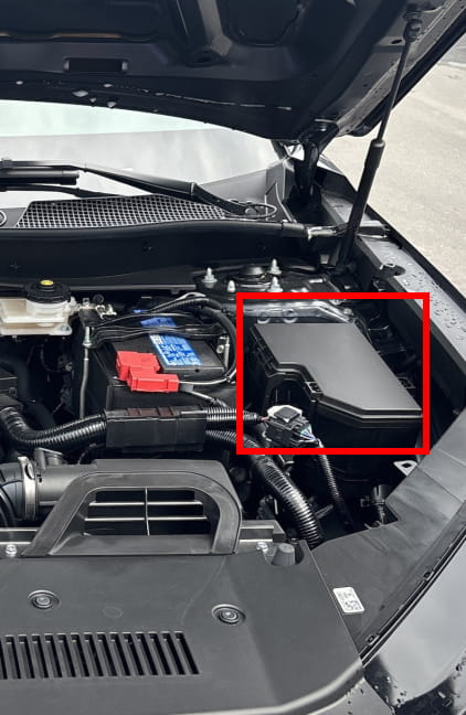
The fuse distribution block is located near the battery.

General view.
| Diagram | ||
|---|---|---|

|
||
| No. | Circuit Description | Current (A) |
| 1 | MAIN FUSE — Main battery fuse | 125 A |
| 2 | I/S2 — Ignition switch power 2 | 30 A |
| Spare | 40 A | |
| F/BOX OPTION1 — Fuse box auxiliary power 1 | 60 A | |
| PTC HTR1 — Positive Temperature Coefficient (PTC) cabin heater circuit 1 | 40 A | |
| F/BOX OPTION2 — Fuse box auxiliary power 2 | 60 A | |
| Spare | 60 A | |
| F/BOX MAIN1 — Interior fuse box main power 1 | 60 A | |
| 3 | AUDIO AMP — Audio system amplifier | 30 A |
| ST MAGNETIC SW — Starter solenoid | 30 A | |
| PTC HTR3 — Positive Temperature Coefficient (PTC) cabin heater circuit 3 | 40 A | |
| RR DEF — Rear window defogger | 30 A | |
| Spare | 50 A | |
| HTR MTR — Heater blower motor | 40 A | |
| PTG MTR — Power tailgate motor | 40 A | |
| 4 | ABS/VSA FSR — ABS / VSA failsafe relay | 40 A |
| ABS/VSA MTR — ABS / VSA modulator motor | 40 A | |
| Spare | 40 A | |
| E BOOSTER — Electric brake booster | 40 A | |
| IG1 MAIN1 — Ignition line main power 1 | 30 A | |
| Spare | 40 A | |
| IG1 MAIN2 — Ignition line main power 2 | 30 A | |
| 5 | I/S1 — Ignition switch power 1 | 30 A |
| WIPER — Windshield wiper motor | 30 A | |
| EPS — Electric Power Steering (EPS) | 70 A | |
| Spare | 30 A | |
| Spare | 40 A | |
| F/BOX MAIN2 — Interior fuse box main power 2 | 60 A | |
| 6 | SUB FAN — Radiator cooling sub-fan motor | 30 A |
| 7 | SRM2 — System Relay Module 2 | 20 A |
| 8 | Spare | — |
| 9 | BACK UP — Backup power (module memory, reverse lights circuit) | 10 A |
| 10 | FR WIPER DEICER — Front wiper de-icer | 15 A |
| 11 | RR FOG — Rear fog light | 10 A |
| 12 | Spare | — |
| 13 | AUDIO SUB — Audio system sub-power | 7.5 A |
| 14 | Spare | — |
| 15 | FR FOG — Front fog lights | 10 A |
| 16 | Spare | — |
| 17 | A/C MG CLUTCH — A/C compressor clutch | 10 A |
| 18 | HORN — Horn | 15 A |
| 19 | FR WASHER — Front windshield washer pump motor | 15 A |
| 20 | AUDIO — Audio system / Infotainment head unit | 15 A |
| 21 | SRM1 — System Relay Module 1 | 20 A |
| 22 | DBW — Electronic throttle actuator (Drive-by-Wire) | 15 A |
| 23 | HAZARD — Hazard warning lights | 10 A |
| 24 | VBU — Body Control Module (BCM) | 10 A |
| 25 | IGP — Engine management system main power (ignition coils, sensors) | 15 A |
| 26 | TCU — Transmission Control Unit (AT / CVT) | 10 A |
| 27 | LCM L — Left LED Control Module | 20 A |
| 28 | INJ — Fuel injectors | 20 A |
| 29 | STOP — Brake light circuit | 10 A |
| 30 | LCM R — Right LED Control Module | 20 A |
| 31 | IG COIL — Ignition coils | 15 A |
| 32 | Spare | — |
| 33 | Spare | — |
| 34 | Spare | — |
| 35 | Spare | — |
| 36 | AUDIO MAIN VST — Audio system main power (VST bus) | 15 A |
| 37 | AUDIO SUB VST — Audio system sub-power (VST bus) | 7.5 A |
| 38 | Spare | — |
| 39 | IGPS VBACT — Ignition control system power (VBACT circuit) | 7.5 A |
| 40 | IGPS FAN — Cooling fan control relay power | 7.5 A |
| 41 | IGPS LAF — Linear Air-Fuel (LAF) wideband oxygen sensor heater power | 7.5 A |
| 42 | IG1 MON2 — Ignition line 2 monitoring circuit | 5 A |

|
||
| M20 | Radiator cooling fan motor relay | — |
| M15 | Rear window defogger relay | — |
| M17 | Heater blower motor relay | — |
| M12 | A/C compressor clutch relay | — |
| M10 | PGM-FI main relay 2 (Engine management) | — |
| M11 | Electric oil pump relay | — |
| M14 | Horn relay | — |
| M7 | PGM-FI main relay 1 (Engine management) | — |
| M6 | PGM-FI sub-relay | — |
| M8 | Fuel injector relay | — |
| M9 | Ignition coil relay | — |
| M1 | Cooling fan control relay | — |
| M3 | Heated steering wheel relay | — |
| M5 | A/C condenser fan motor relay | — |
