Most of the electrical circuits in the electrical equipment of the Japanese minivan are protected by fuses. Headlights, fan motors, fuel pump and other powerful current consumers are connected via relays. Protective elements are installed in distribution boxes, which are located in the engine compartment and the passenger compartment.

Considered models Honda Mobilio (GB body) 2001, 2002, 2003, 2004, 2005, 2006, 2007, 2008 release 2WD & 4WD with an L15A engine (1.5 liters)., As well as Mobilio Spike (GK body).
In the passenger compartment
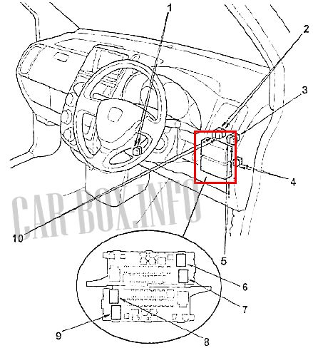
Location of components under the dashboard.
1 - the main relay of the injection system No. 1, the main relay of the injection system No. 2,
2 - the horn relay, the relay of the connector for connecting additional equipment (models with air conditioning with automatic control),
3 - the relay of the heater fan motor,
4 - the relay of the right direction indicators, left turn indicator relay,
5 - headlight relay No.1 (models with gas-discharge headlights), headlight relay No.2 (models with gas-discharge headlights), headlight relay (models with halogen headlights),
6 - reversing light relay,
7 - electric drive relay window lifters,
8 - starter disconnect relay,
9 - parking lamps relay,
10 - closing relay, opening relay (central locking).
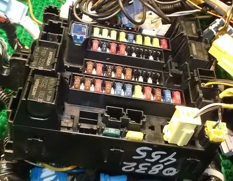
The photo shows an example.
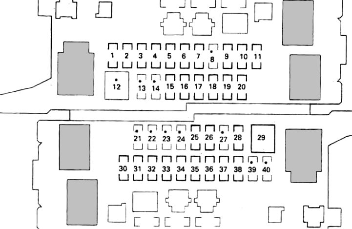
| Interior fuse box diagram | ||
|---|---|---|
|
||
| No. | Description | A |
| 1 | Passive safety unit (VB) | 10 |
| 2 | Passive safety system (VA) unit, engine control unit, fuel pump fuse | 15 |
| 3 | Front passenger position detection unit (models with side airbags) | 7.5 |
| 4 | Power window relay, driver's door power window control unit (integrated in the main power window control switch), rear window wiper motor | 10 |
| 5 | Windshield wiper motor, windshield washer pump | 20 |
| 6 | Ignition coils (front) | 15 |
| 7 | Ignition coils (rear) | 15 |
| 8 | No | - |
| 9 | Direction indicator and hazard warning light control circuit (built into the instrument cluster) | 10 |
| 10 | Alternator, oxygen sensor, sunroof control unit, EPS control unit, selector lever lock solenoid valve, instrument cluster, central locking remote control unit, pressure modulator and ABS electronic control unit, supply voltage monitoring system unit, EVAP control valve | 7.5 |
| 11 |
|
7.5 |
| 12 | No | - |
| 13 | - | |
| 14 | - | |
| 15 | - | |
| 16 | Cooling Fan Motor Relay, Condenser Fan Motor Relay, A / C Compressor Clutch Relay, Rear Window Defogger Relay, Heater Blower Motor Relay, Air Intake Switching Drive, A / C and Heater Control Panel | 7.5 |
| 17 | Power mirrors | 7.5 |
| 18 | No | - |
| 19 |
|
10 |
| 20 | Ignition key lock solenoid valve, ignition key lock control circuit (built into the instrument cluster), navigation system unit (models with navigation system), TV tuner (models with navigation system), audio system unit (models without navigation system) | 7.5 |
| 21 | No | - |
| 22 | - | |
| 23 | - | |
| 24 | - | |
| 25 |
|
10 |
| 26 |
|
10 |
| 27 | No | - |
| 28 | Diagnostic socket, navigation system unit, audio system unit (models without navigation system), remote control unit for central locking, local illumination lamp, front interior lighting lamp, rear interior lighting lamp, TV tuner (models with navigation system), electric drive control unit sliding door | 10 |
| 29 | Front accessory connector (auto air conditioning models), rear accessory connector (auto air conditioning models) | 20 |
| 30 |
|
10 |
| 31 | Electric drive of door locks | 20 |
| 32 | Sunroof drive motor | 20 |
| 33 |
|
20 |
| 34 | The engine control unit | 15 |
| 35 | Power window relay | 20 |
| 36 | Driver's door power window | 20 |
| 37 | Control unit for the electric drive of the left sliding door | 20 |
| 38 | Control unit for the electric drive of the right sliding door | 20 |
| 39 | No | - |
| 40 | - | |
| Relay | ||
|
||
| 14 | Starter cutout relay | |
| 13 | parling lights re;ay | |
| 7 | electric windows | |
| 6 | Reversing light relay | |
| Rest: either wiring harnesses or not used. | ||
In the engine compartment
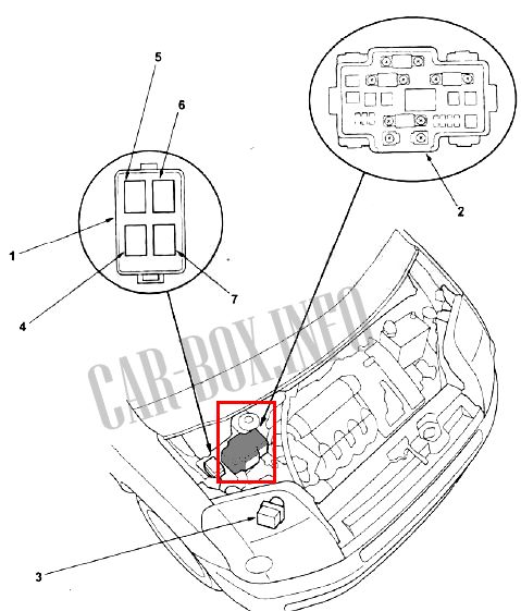
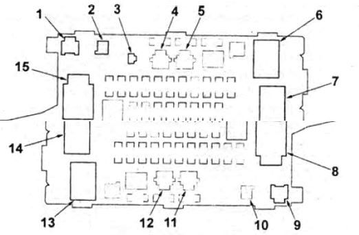
Location of components. 1 - relay holder, 2 - fuse block in the engine compartment, 3 - pressure modulator and ABS electronic control unit, 4 - air conditioning compressor electromagnetic clutch relay, 5 - cooling fan motor relay, 6 - rear window defogger relay, 7 - motor relay condenser fan.
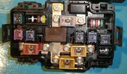
General view of the distribution box.
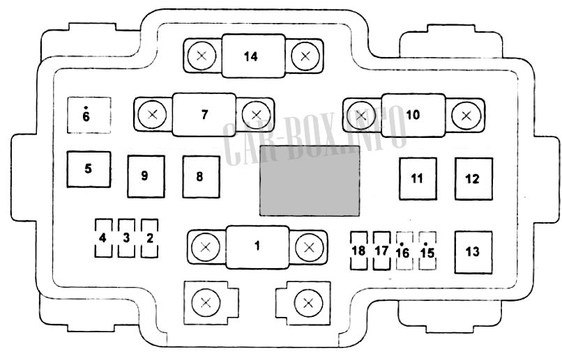
| Fuse diagram in the engine compartment (No. 2 in the picture) | ||
|---|---|---|
|
||
| No. | Decoding | A |
| 1 | Accumulator battery | 100 |
| 2 | Direction indicator and hazard warning light control circuit (built into the instrument cluster), direction indicators | 10 |
| 3 | Horn switch, horn, pressure modulator and ABS electronic control unit, engine control unit, brake lights, auxiliary brake light, selector lock control circuit (built into the instrument cluster) | 10 |
| 4 | Pressure modulator and ABS electronic control unit | 30 |
| 5 | 40 | |
| 6 | No | - |
| 7 | EPS control unit | 60 |
| 8 | Heater fan motor | 40 |
| 9 | Cooling fan motor | 20 |
| 10 | Ignition lock (output "+ B") | 50 |
| 11 | Heated rear window | 20 |
| 12 | Fuses No. 17, 18 in the distribution box in the engine compartment | 30 |
| 13 | Fuses No. 28, 29 in the distribution box under the dashboard | 40 |
| 14 | Fuses No. 30 - 38 in the distribution box under the dashboard | 60 |
| 15 | No | - |
| 16 | - | |
| 17 | A / C Compressor Electromagnetic Clutch | 7.5 |
| 18 | Condenser fan motor | 20 |
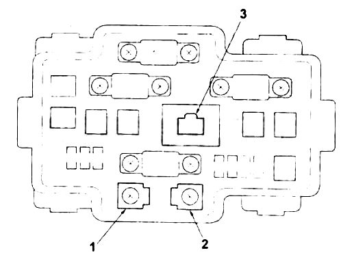
|
||
| 3 | Supply Voltage Monitor (ELD) | |
| 1 | T-1: Engine compartment wiring harness | |
| 2 | T-101: Engine wire harness | |
