Table of Contents
Most of the electrical circuits in the electrical equipment of the Japanese minivan are protected by fuses. Protective elements are installed in distribution boxes located in the engine compartment and passenger compartment.

In this article, we will take a detailed look at the fuse box diagrams for the Honda Odyssey 4th generation (RB3, RB4) 2008, 2009, 2010, 2011, 2012, 2013 release.
In the passenger compartment
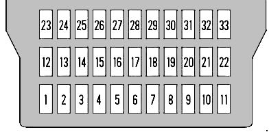
Primary fuse box

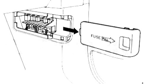
Located on the driver's side behind a plastic cover.
| Diagram | ||
|---|---|---|
|
||
| No. | Decoding | A |
| 1 | TPMS (Tire Pressure Monitoring Module) | 7.5 |
| 2 | Ignition coil | 15 |
| 3 | Daytime Running Lights | 10 |
| 4 | LAF (oxygen sensor) | 15 |
| 5 | Radio | 10 |
| 6 | Interior lighting | 7.5 |
| 7 | Reverse | 7.5 |
| 8 | Not used | - |
| 9 | Cigarette lighter fuse Honda Odyssey | 15 |
| 10 | OPDS | 7.5 |
| 11 | Wiper | 30 |
| 12 | Rear outlet (cigarette lighter) | 15 |
| 13 | Left sliding door closer | 20 |
| 14 | Power seat | 20 |
| 15 | Electronic Pedal (Pedal Position Adjustment) | 20 |
| 16 | Power seat | 20 |
| 17 | Rear door closer | 20 |
| 18 | ACG | 15 |
| 19 | Fuse pump fuse | 15 |
| 20 | Washer | 10 |
| 21 | Instrument cluster | 7.5 |
| 22 | SRS | 10 |
| 23 | Engine control unit (IGP) | 7.5 |
| 24 | Rear left power window | 20 |
| 25 | Rear right power window | 20 |
| 26 | Passenger side window lifter | 20 |
| 27 | Driver's side window regulator | 20 |
| 28 | Sunroof | 20 |
| 29 | Not used | - |
| 30 | Steep Hill Vehicle Control (HAC) | 10 |
| 31 | SOL | 15 |
| 32 | Air conditioning | 10 |
| 33 | Steep Hill Vehicle Control (HAC) | 7.5 |
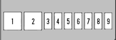
Auxilary fuse panel
Located on the passenger side, behind a plastic cover.
| Diagram | ||
|---|---|---|
|
||
| No. | Description | A |
| 1 | Rear heater | 30 |
| 2 | Not used | - |
| 3 | Electronic Throttle Control System (DBW) | 15 |
| 4 | central locking | 20 |
| 5 | Not used | - |
| 6 | Seat heating | 15 |
| 7 | Dashboard | 7.5 |
| 8 | Right sliding door closer | 20 |
| 9 | No | - |
In the engine compartment
Primary fuse box
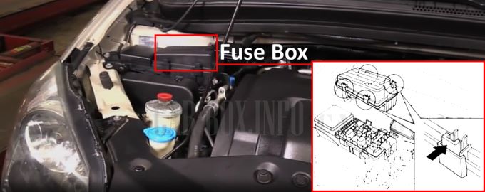
The location of the main unit in the engine compartment.
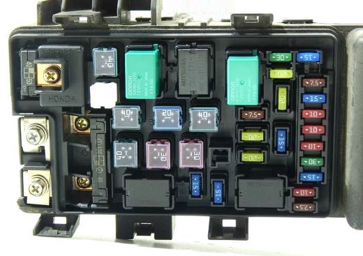
General view.
| Diagram | ||
|---|---|---|

|
||
| No. | Appointment | A |
| 1 | Left low beam | 10 |
| 2 | Heated rear window | 30 |
| 3 | Left high beam | 10 |
| 4 | parking lights | 15 |
| 5 | Right low beam | 10 |
| 6 | Right high beam | 10 |
| 7 | Reverse | 7.5 |
| 8 | FI ECU, diagnostic socket | 15 |
| 9 | Air conditioner fan | 30 |
| 10 | No | - |
| 11 | Cooling fan | 30 |
| 12 | Electromagnetic clutch | 7.5 |
| 13 | Stop lights, horn | 20 |
| 14 | Heated rear window | 30 |
| 15 | Reverse | 40 |
| 16 | Alarm | 15 |
| 17 | VSA / ABS | 30 |
| 18 | VSA / ABS | 30 |
| 19 | A computer | 30 |
| 20 | Folding seat drive | 40 |
| 21 | Heater | 40 |
| 22 | + B AS F / B (sliding doors) | 70 |
| Battery | 120 | |
| 23 | + B IGI Main (ignition) | 50 |
| Window lifters | 40 50 |
|
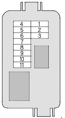
Auxilary fuse panel
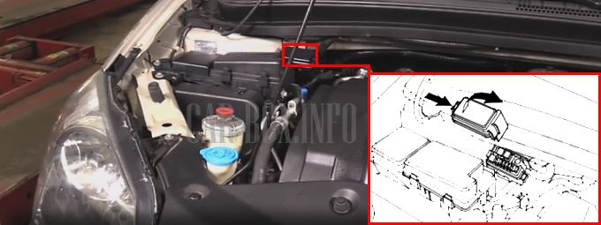
The location of the additional unit in the engine compartment.
| Diagram | ||
|---|---|---|
|
||
| No. | Protected circuit | A |
| 1 | Not used | - |
| 2 | Sliding door on the left side | 40 |
| 3 | Sliding door on the right side | 40 |
| 4 | Backdoor | 40 |
| 5 | Premium | 20 |
| 6 | AC inverter | 20 |
| 7 | Front fog lights | 20 |
| 8 | ACM | 10 |
| 9 | Power seat | 20 |
| 10 | Power seat | 20 |
| 11 | Rear Passenger Entertainment System | 7.5 |
View and print PDF:
