
The fourth-generation Hyundai Sonata was introduced in August 1998. It was powered by 2.0L (136 hp) and 2.4L (138 hp / 103 kW) Sirius inline-four engines, as well as a 2.5L V6 DOHC Delta engine producing 168 hp (121 kW). In this guide, we provide a detailed overview of the fuse box diagrams for the fourth-generation Hyundai Sonata (chassis code EF) for model years 1998, 1999, 2000, 2001, 2002, 2003, and 2004.

Here you will find fuse box locations, diagrams, and panel photos. Fuses responsible for key components such as the “Cigarette Lighter” and “Fuel Pump” are highlighted in bold.
Engine Compartment
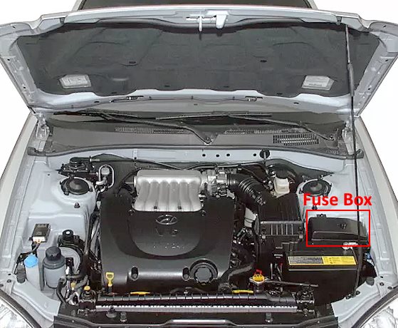
The engine compartment fuse box is located next to the battery under a protective cover.

General view.
| Diagram | ||
|---|---|---|

|
||
| Name | Circuit Protected | Amps |
| HORN | Horn relay | |
| HDLP_LOW | Headlamp relay | |
| RAD FAN_HI | Radiator fan relay (High) | |
| RAD FAN_LOW | Radiator fan relay (Low) | |
| F / PUMP | Fuel pump relay | |
| WIPER | Windshield wiper relay | |
| START | Starter relay | |
| A / CON | Air conditioning relay | |
| ATM CONT | Transmission Control Module (TCM) relay | |
| COMD FAN | A/C condenser fan motor | 20 |
| PWRWIND | Power windows | 40 |
| ABS 2 | Anti-lock braking system (ABS) | 30 |
| IGN SW-1 | Ignition switch | 30 |
| ABS 1 | Anti-lock braking system (ABS) | 30 |
| IGN SW-2 | Ignition switch | 30 |
| RAD FAN MTR | Radiator fan motor | 30 |
| 1 FUEL PUMP | Fuel pump | 20 |
| 2 HD LP LO | Low-beam headlamps | 15 |
| 3 ABS | Anti-lock braking system (ABS) module | 10 |
| 4 INJECTOR | Fuel injectors | 10 |
| 5 A / C COM PR | A/C compressor clutch | 10 |
| 6 ATM RLY | Automatic transmission relay | 20 |
| 7 ECURLY | Engine Control Module (ECM) relay | 30 |
| 8 IG COIL | Ignition coils, ignition failure sensor | 20 |
| 9 OZSNSR | Oxygen (O2) sensor | 15 |
| 10 ECU | Engine Control Module (ECM), fuel pump relay, PCV solenoid valve, idle speed control valve, crankshaft position (CKP) sensor | 15 |
| 11 HORN | Horn | 10 |
| 12 HEAD LP HI | High-beam headlamps | 15 |
| 13 HEAD LP WASH | Headlamp washer motor | 20 |
| 14 DRL | Daytime running lights (DRL), anti-theft system | 15 |
| 15 FRFOG | Front fog lamps | 15 |
| 16 HEAD LP LO RH | HID / Xenon headlamp (RH) | 15 |
| 17 SPARE | Spare | 30 |
| 18 SPARE | Spare | 20 |
| 19 SPARE | Spare | 15 |
| 20 SPARE | Spare | 10 |
| 21 BLOWER | Blower motor | 30 |
| 22 PWR FUSE-2 | Power fuse 2 | 30 |
| 23 FWRAMP | Audio power amplifier | 20 |
| 24 SUNROOF | Sunroof module, Data Link Connector (DLC) | 15 |
| 25 VAIL LP | Tail lamp relay | 20 |
| 26 PWR FUSE-1 | Power fuse 1, passenger compartment fuse panel (fuses 2, 3, 7, 8, 9) | 30 |
| 27 ECU | Engine Control Module (ECM) | 10 |
| 28 RR HTD | Rear window defogger and heated side mirror relay | 30 |
Passenger Compartment

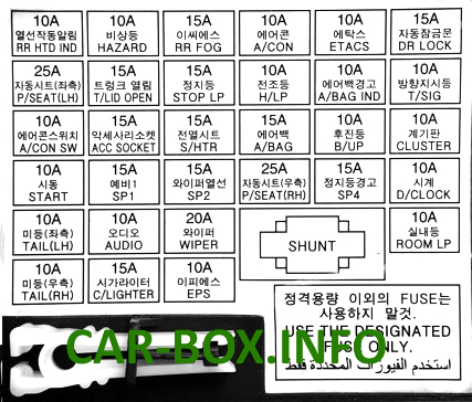
Located at the bottom of the driver's side dashboard. Remove the protective cover for access.

General view of the Hyundai Sonata (EF) interior fuse box.
| Diagram | ||
|---|---|---|
|
||
| Name | Description | Amps |
| A / CON | Air conditioning system | 10 |
| ETACS | ETACS module, keyless entry, power door locks | 10 |
| DR LOCK | Power door locks | 15 |
| P / SEAT | Power seat | 25 |
| T / LID OPEN | Remote trunk lid release | 15 |
| STOP LP | Brake lamps | 15 |
| H / LP | Headlamps | 10 |
| A / BAG IND | Airbag (SRS) indicator | 10 |
| T / SIG | Turn signals | 10 |
| A / CON SW | Air conditioning switch | 10 |
| ACC SOCKET | 12V Auxiliary power outlet | 15 |
| S / HTR | Heated seats | 15 |
| A / BAG | Airbag (SRS) module | 15 |
| B / UP | Backup lamps | 10 |
| CLUSTER | Instrument cluster, combination lamps | 10 |
| START | Starter signal | 10 |
| SP1 | Spare | 15 |
| SP2 | Spare | 15 |
| P / SEAT (RH) | Power seat (RH) | 25 |
| SP4 | Spare | 15 |
| D / CLOCK | Digital clock | 10 |
| TAIL (LH) | Left parking lights, license plate lamps, left tail lamps | 10 |
| AUDIO | Audio system | 10 |
| WIPER | Windshield wipers | 20 |
| ROOM LP | Interior dome lights, front door courtesy lamps | 10 |
| TAIL (RH) | Right parking lights, license plate lamps, right tail lamps | 10 |
| C / LIGHTER | Cigarette lighter | 15 |
| EPS | Electronic Power Steering (EPS) | 10 |
The relays are mounted on the rear side of the junction block.

Legend:
- A – Power connector;
- B – ETACS control module connector;
- C – Door lock relay No. 1;
- D – Door lock relay No. 2;
- E – Alternator field winding resistor;
- F – Tail lamp relay;
- G – Power window motor relay;
- H – Rear window defogger and side mirror heater relay.
