
Production of the third-generation Hyundai Elantra began in 2000. Starting in 2001, North American market models came standard with airbags, air conditioning, central locking, power windows, and power steering. The vehicle underwent a mid-cycle facelift in 2003. This guide provides detailed fuse and relay box diagrams, panel locations, and circuit assignments for the Hyundai Elantra (third generation; XD chassis) covering the 2000, 2001, 2002, 2003, 2004, 2005, and 2006 model years.

Below you will find location diagrams and photos of the power distribution centers. Circuits for the “Cigarette Lighter” and “Fuel Pump” are highlighted in bold.
Engine Compartment
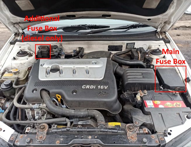
Depending on the engine configuration (gasoline or diesel), the engine bay contains either one or two fuse blocks.
Main Fuse Box
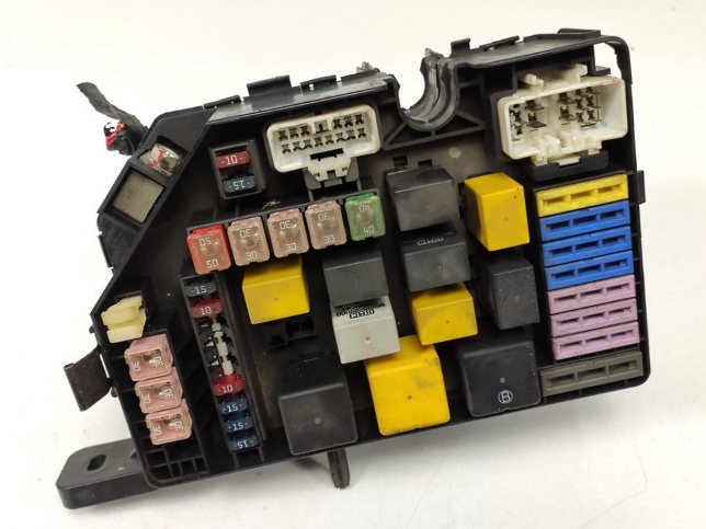
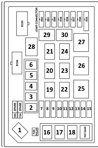
Located on the left (driver) side of the engine compartment, adjacent to the battery.
| Diagram | ||
|---|---|---|
|
||
| No. | Description | A |
| 1 | BATT - Main fuselink | 120 |
| 2 | BATT - Power windows, tail lamps, interior fuses #4, #13, #14, #15, #16 | 50 |
| 3 | COND - A/C condenser fan switch | 20 |
| 4 | RAD - Radiator cooling fan switch | 20 |
| 5 | ECU - Engine Control Module, fuel pump relay circuit | 20 |
| 6 | IGN - Ignition switch, starter circuit | 40 |
| 7 | INJ - Fuel injectors, idle air control (IAC) valve, EVAP purge control valve, camshaft position sensor | 15 |
| 8 | SNSR - Heated oxygen sensor (HO2S), Engine Control Module (ECM) | 10 |
| 9 | DRL - Daytime running lights system | 15 |
| 10 | H / WASH - Headlamp washer motor (if equipped / unused) | 20 |
| 11 | F / FOG - Front fog lamps | 15 |
| 12 | ECU - Transmission Control Module (TCM) | 10 |
| 13 | HORN A / C - Horn, A/C compressor magnetic clutch relay | 15 |
| 14 | H / LP (HI) - High-beam headlamps | 15 |
| 15 | H / LP (LO) - Low-beam headlamps | 15 |
| 16 | ABS1 - Anti-lock braking system (ABS control unit) | 30 |
| 17 | ABS2 - Anti-lock braking system (ABS hydraulic pump) | 30 |
| 18 | BLOWER - HVAC blower motor | 30 |
| 19 | HEAD LAMP HI - High-beam headlamp relay | |
| 20 | A / C - A/C compressor clutch relay | |
| 21 | FUEL PUMP - Fuel pump relay | |
| 22 | FRONT FOG LAMP - Front fog lamp relay | |
| 23 | WIPER MOTOR - Windshield wiper motor relay | |
| 24 | HORN - Horn relay | |
| 25 | CONDENSER FAN 2 - A/C condenser fan relay 2 | |
| 26 | ENGINE CONTROL UNIT - Engine control main relay | |
| 27 | START - Starter motor relay | |
| 28 | CONDENSER FAN 1 - A/C condenser fan relay 1 | |
| 29 | HEAD LAMP LOW - Low-beam headlamp relay | |
| 30 | RADIATOR FAN - Radiator cooling fan relay | |
Auxiliary Fuse Box
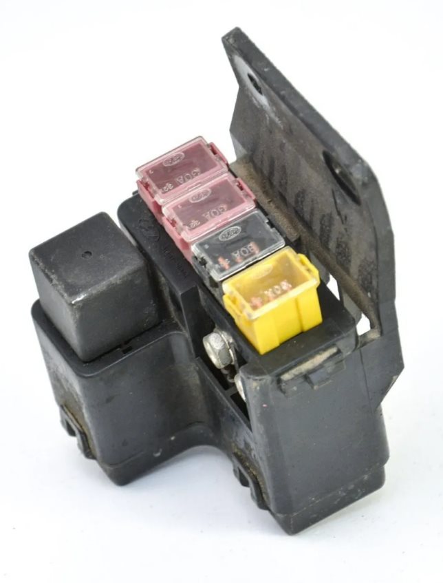
Fitted exclusively on diesel-engine variants.
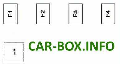
Legend:
- 1 - Glow plug relay;
- F1 - Fuel heater (30A);
- F2 - Auxiliary coolant heater (30A);
- F3 - Glow plug main circuit (80A);
- F4 - Auxiliary coolant heater (60A).
Passenger Compartment
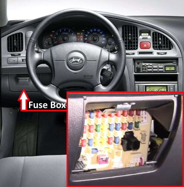
Located behind the coin tray / storage compartment on the driver's side of the lower instrument panel.
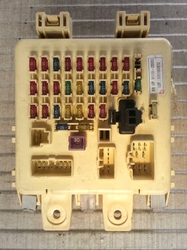
Overview of the Hyundai Elantra (Gen 3) interior junction block.
| Diagram | ||
|---|---|---|
|
||
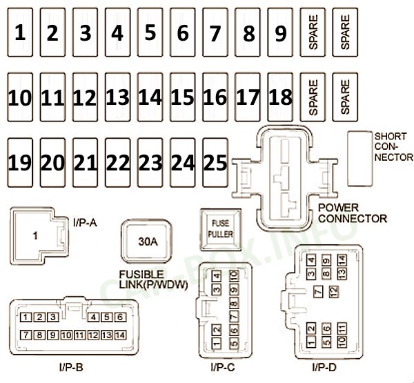
| No. | Description | Amps |
| 1 | Turn signals, back-up (reverse) lamps | 10 |
| 2 | Instrument cluster illumination, DRL, alternator field circuit, windshield wiper intermittency module, anti-theft security system | 10 |
| 3 | Supplemental Restraint System (SRS / Airbags) | 15 |
| 4 | Hazard warning flasher switch | 10 |
| 5 | HVAC blower motor relay control | 10 |
| 6 | Right headlamp, interior dome lamp switch | 10 |
| 7 | Left headlamp, exterior clearance illumination | 10 |
| 8 | Anti-theft security system, starter relay control circuit | 10 |
| 9 | Digital clock, power mirrors, audio unit | 10 |
| 10 | Cruise control system, ECM, Transmission Control Module (TCM), electronic speedometer | 10 |
| 11 | Anti-lock braking system (ABS control module) | 10 |
| 12 | SRS / Airbag warning indicator lamp | 10 |
| 13 | Rear window defogger grid | 30 |
| 14 | Power antenna motor | 20 |
| 15 | Central door locking system, power sunroof controller | 15 |
| 16 | Stop lamps, power window relay control | 15 |
| 17 | Rear window defogger and heated exterior mirrors | 10 |
| 18 | Cigarette lighter and 12V auxiliary power socket | 15 |
| 19 | Not used (Spare slot) | 10 |
| 20 | A/C control unit, headlamp leveling system, power window control switch | 10 |
| 21 | Rear window wiper motor and washer pump | 15 |
| 22 | Windshield wiper motor and washer pump | 20 |
| 23 | Heated front seats | 20 |
| 24 | Automatic climate control, wiper variable delay unit, auto-dimming mirror, power sunroof | 10 |
| 25 | Interior dome lamp, trunk illumination, ignition key cylinder light, Data Link Connector (OBD-II DLC), audio system memory | 15 |
| Short connector |
Short Connector (Jumper): Glove box lamp, audio system, climate control memory | - |
| P / WDW | Power window circuit breaker | 30 |
| spare | Spare fuse storage | - |
Additional relay modules are mounted on the reverse side of the junction block.
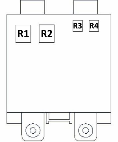
Legend:
- R1 - Rear window defogger relay;
- R2 - Power window relay;
- R3 - Charge warning indicator relay;
- R4 - Tail lamp relay.
