In early May 2010, the 5th generation Hyundai Elantra was unveiled at the Busan International Motor Show, which was sold as Avante in the South Korean domestic market. In this article, we will take a detailed look at the fuse box diagrams for the Hyundai Elantra (fifth generation; MD / UD index) 2010, 2011, 2012, 2013, 2014 and 2015 years of manufacture.

Here you will find the locations and photos of distribution boxes. The fuses responsible for the “Cigarette lighter” and “Fuel Pump” are highlighted in bold.
In the engine compartment
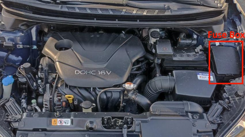
It is located behind the protective cover on the left side of the underhood.
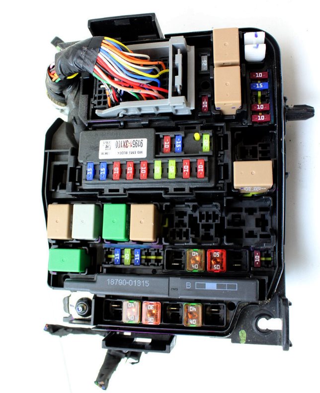
General view.
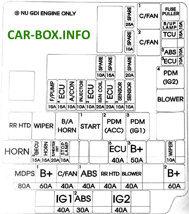
| Diagram | ||
|---|---|---|
|
||
| Name | Description | Amps |
| MDPS | EPS control module | 80 |
| B + 1 | Distribution block (ARISU 1 (4CH), IPS 1, Fuse - P / WDW LH, P / WDW RH, TRUNK, AMP 1) | 60 |
| C / FAN | Cooling Fan Relay (Low), Cooling Fan Relay (High) | 40 |
| ABS 1 | ESC Module, Multifunction Diagnostic Connector | 40 |
| RR HTD | Seat heating relay | 40 |
| BLOWER | Cooling fan relay | 40 |
| B + 2 | Distribution block (Horn relay when the turn signal is turned on, ARISU 2 (4CH), IPS (1CH), IPS (2CH), Fuses - P / SEAT DRV, SUNROOF [SUNROOF]) | 60 |
| B / UP LP | Electrochromic mirror, audio/video (A/V) and navigation head unit module, taillight combination (interior) left/right, brake light switch, BCM, instrument cluster | 10 |
| TCU 1 | Vehicle speed sensor, Automatic transmission mode switch | 15 |
| ABS3 | ESC System Module, Multi Function Diagnostic Connector | 10 |
| ECU3 | Stop Lamp Switch, ECM, Automatic Transmission - PCM | 10 |
| WIPER | Rain sensor, ECM, automatic transmission - PCM | 10 |
| B + 3 | Distribution block (Fuses - MODULE 1, PDM 1, PDM 2, DR LOCK) | 50 |
| EMS | EMS Unit (Engine Control Relay, Fuses - ECU 4, A / CON, F / PUMP) | 40 |
| STOP LP | Brake Light Switch, Smart Key System Control Module | 15 |
| S / HEATER FRT | Driver and passenger seat heating control module | 20 |
| HORN | Horn relay | 15 |
| IG2 |
|
40 |
| ABS 2 | ESC System Module, Multifunction Diagnostic Socket | 30 |
| IG 1 |
|
40 |
| F / PUMP | Fuel pump relay | 15 |
| ECU 4 | PCM (automatic transmission), ECM (manual transmission) | 15 |
| A / CON | A / C compressor relay | 10 |
| INJECTOR | Fuel Injectors # 1 / # 2 / # 3 / # 4, A / C Compressor Relay, Fuel Pump Relay | 10 |
| ECU 2 | PCM (automatic transmission), ECM (manual transmission) | 10 |
| IGN COIL1 | Ignition Coils # 1 / # 2 / # 3 / # 4, Capacitor | 20 |
| SENSOR 2 | Immobilizer System Module, Camshaft Position Sensor # 1 / # 2 | 10 |
| SENSOR 1 | Excess oxygen sensor (upper / lower), Additional fuel tank closure valve, Intake manifold length change solenoid valve, Oil pressure control valve with camshaft position change #1 / #2, Exhaust system solenoid valve, Engine cooling fan relay (low), Engine cooling fan relay (high) | 10 |
| SPARE | Reserve | - |
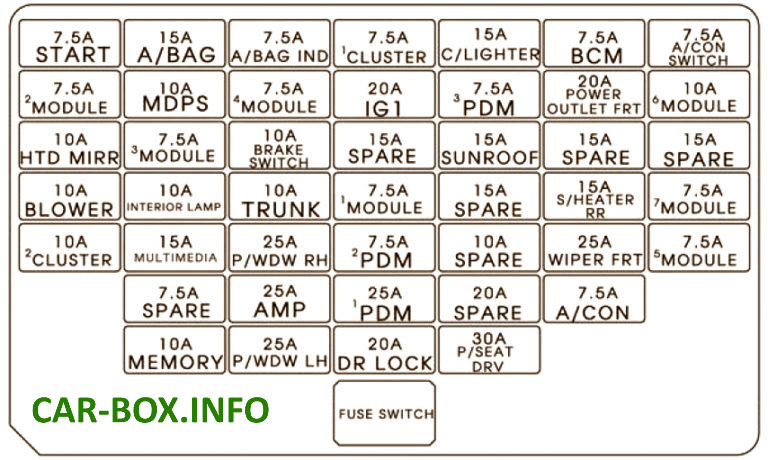
In the passenger compartment
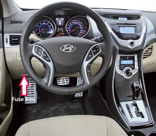
Located behind the protective cover on the driver's side of the dashboard.
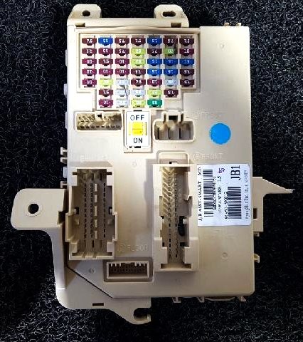
General view of the Hyundai Elantra 5 interior fuse box.
| Diagram | ||
|---|---|---|
|
||
| Name | Circuit Protected | A |
| START |
|
7.5 |
| A / BAG | SRS Control Module, Passenger Mass Classification Sensor | 15 |
| A / BAG IND | Instrument panel | 7.5 |
| MDPS | Power steering EPS control module | 7.5 |
| POWER OUTLET | Power outlet (12V sockets) | 15 |
| BCM | Smart Key System Control Module, BCM | 7.5 |
| A / CON SW | Air conditioning control module | 7.5 |
| MODULE 2 | Electro chrome mirror, ESC switch | 7.5 |
| SPARE 1 | Reserve | - |
| MODULE 4 | Rear left/right rear parking assist sensor (inside/outside), air conditioning control module (climate control), automatic transmission selector lever position indicator | 7.5 |
| IG1 | Fuse and relay box E / R (Fuse - TCU 1, ECU 3, ABS 3) | 20 |
| PDM3 | Smart Key system control module | 7.5 |
| C / LIGHTER | Hyundai Elantra cigarette lighter fuse | 20 |
| MODULE 6 | Exterior mirror adjustment switch, audio, audio and navigation head unit module, digital clock | 10 |
| HTD MIRR | Outside mirror adjustment switch Driver / Passenger, Air conditioning control module | 10 |
| MODULE 3 | Audio, tire pressure monitoring system module, digital clock, BCM, instrument cluster, driver and passenger seat heating module | 7.5 |
| SUNROOF | Sunroof module | 15 |
| S / HEATER RR RH | Rear right seat heating switch | 15 |
| BLOWER | A / C Control Module (Manual Air Conditioner), ECM / PCM, Blower Resistor | 10 |
| IOD 1 | Trunk lamp, left/right individual light bulbs, interior lamp, overhead console lamp, ignition switch III. and open door warning switch (without Smart Key system) | 10 |
| TRUNK | Trunk lid relay | 10 |
| MODULE 1 | Transmission shift to sport mode, key solenoid (without Smart Key system) | 7.5 |
| S / HEATER RR LH | Heated rear left seat heater switch, left side | 15 |
| MODULE 7 | Smart Key System Control Module, BCM | 7.5 |
| IOD 2 | Audio systems, Head unit A / V and navigation | 20 |
| P / WDW RH | Right power window relay | 25 |
| PDM2 | Smart Key System Control Module, Start Stop Button Switch | 7.5 |
| WIPER FRT | ICM Fuse / Relay Box (Rain Sensor Relay), Multifunction Switch, Wiper Motor, E / R Fuse / Relay Box (Wiper Relay) | 25 |
| MODULE 5 | Ionizer (Climate control), Rain sensor, Roof hatch | 7.5 |
| AMP 1 | AMP (amplifier) | 25 |
| PDM 1 | Smart Key System Control Module | 25 |
| A / CON | A / C Control Module, E / R Fuse and Relay Box (Blower Relay) | 7.5 |
| IOD 4 | Tire pressure monitoring system module, BCM, headlight photo light sensor, instrument cluster, DLC, distribution block upgrade connector, electrochromic mirror, air conditioning control module, digital clock | 10 |
| P / WDW LH | Left Power Window Relay, Power Windows Safety System Module | 25 |
| DR LOCK | Door Lock Relay, Door Unlock Relay, ICM Fuse and Relay Box (Turn Signal Relay) | 20 |
| P / SEAT DRV | Switch for manual adjustment of the driver's seat | 30 |
