The Elantra 6 made its North American debut in November 2015 at the Los Angeles Auto Show and went on sale in the United States in January 2016 and in Canada in February 2016. In this article, we will take a detailed look at the fuse box diagrams for the Hyundai Elantra (sixth generation; index AD) 2015, 2016, 2017, 2018, 2018, 2019, 2020 years of manufacture.

Here you will find the locations and photos of distribution boxes. The fuses responsible for the “Cigarette lighter” and “Fuel Pump” are highlighted in bold.
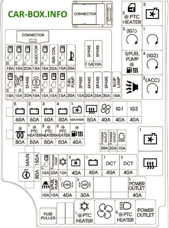
In the engine compartment

Located on the right side under the soot space, next to the battery.
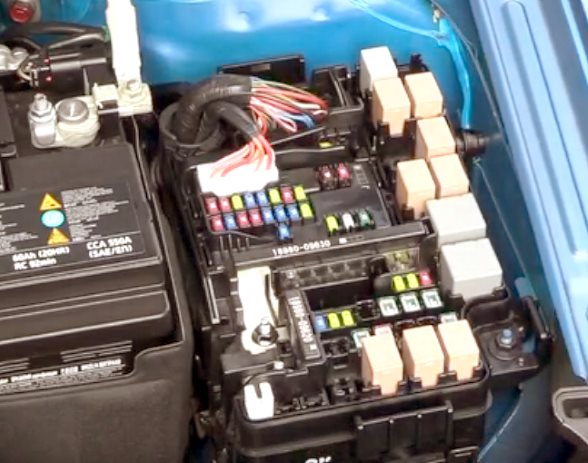
Access example.
| Diagram | ||
|---|---|---|
|
||
| Name | Description | A |
| MAIN | Fuse: ABS1, ABS2, B / ALARM HORN, POWER OUTLET | 180 |
| MDPS | Motor Driven Power Steering Unit | 80 |
| B + 5 | PCB Assembly (Fuse: ECU3, ECU4, HORN, FUEL PUMP, ENGINE CONTROL RELAY) | 60 |
| B + 2 | Smart junction box (fuse: S / HEATER FRT, ARISU) | 60 |
| B + 3 | Intelligent connection box (fuse: ARISU, IPS) | 60 |
| B + 4 | Smart Junction Box (Fuse: S / HEATER FRT, P / WINDOW LH, P / WINDOW RH, TRUNK, SUNROOF, AMP, P / SEAT DRV) | 50 |
| COOLING FAN 1 | Cooling fan | 60 |
| REAR HEATED | Rear heating relay | 50 |
| BLOWER | Fan relay | 40 |
| IG1 | Ignition switch, E / R connection block (PDM relay # 2, # 3 (ACC / IG1)) | 40 |
| IG2 | Ignition switch, E / R junction box (PDM # 4 (IG2) relay, START relay) | 40 |
| B / UP LAMP | Electro Chrome Mirror, Rear Combination Light (IN) L / R, Intelligent Junction Box (IPS Control Module) | 10 |
| POWER OUTLET 3 | Elantra cigarette lighter fuse | 20 |
| POWER OUTLET 2 | front socket | 20 |
| H / LAMP HI | Headlights | 10 |
| TCU 1 | Spare | 15 |
| VACUUM PUMP 1 | Fuel pump | 20 |
| A / CON | air conditioning relay | 10 |
| COOLING FAN 2 | Cooling fan relay 1/2 | 40 |
| B + 1 | Intelligent Junction Box (Leakage Circuit Breaker, Fuse: BRAKE SWITCH, MODULE 1, ENGINE LOCK, PDM 1, PDM 2) | 40 |
| DCT1 | Not used | 40 |
| DCT2 | Not used | 40 |
| B / ALARM HORN | B / Horn relay | 10 |
| S / FUEL PUMP | Fuel pump fuse | 15 |
| ABS 1 | Electronic stability control module, multipurpose control connector | 40 |
| ABS 2 | Electronic stability control module, multipurpose control connector | 30 |
| POWER OUTLET 1 | 12V Socket relay | 40 |
| ECU 5 | Powertrain control module | 10 |
| VACUUM PUMP | Vacuum pump | 15 |
| SPARE | Spare | 20 |
| ABS 3 | Electronic stability control module, multipurpose control connector | 10 |
| TCU 2 | Transmission Range Selector, Reverse / Reverse Junction Box (Fuse: B / UP LAMP) | 15 |
| ECU 4 | Powertrain control module | 15 |
| ECU 3 | Powertrain control module | 15 |
| FUEL PUMP | Fuel pump relay | 20 |
| SENSOR 2 | Canister closing valve, purge control solenoid valve, variable inlet solenoid valve, connection block E/R (cooling fan relay 1/2) | 10 |
| ECU2 | Spare | 10 |
| ECU1 | Powertrain control module | 20 |
| INJECTOR | Injector # 1 / # 2 / # 3 / # 4 | 15 |
| SENSOR 1 | Oxygen sensor (UP / DOWN) | 15 |
| IGN COIL | Ignition coil # 1 / # 2 / # 3 / # 4 | 20 |
| SENSOR 3 | Oil supply control valve No. 1 / No. 2 / No. 3, electronic temperature sensor, fuel pump relay | 10 |
| HORN | Horn relay | 20 |
In the passenger compartment

Located under the dashboard on the driver's side behind the protective cover.
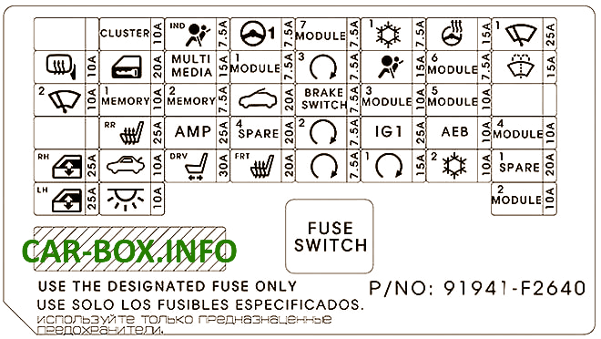
Example of a diagram from the block cover.

General view of the Hyundai Elantra interior fuse box.
| Diagram | ||
|---|---|---|

|
||
| Name | Circuit Protected | A |
| HEATED MIRROR | Driver/passenger power exterior mirror, air conditioning control module | 10 |
| WIPER 2 | PCM, BCM | 10 |
| P / WINDOW RH | right power window relay | 25 |
| P / WINDOW LH | left power window relay, driver safety power window module | 25 |
| CLUSTER | CLUSTER | 10 |
| DR LOCK | Door lock / unlock relay, reverse / reverse connection block (two turn unlock relay) | 20 |
| MEMORY 1 | Driver / passenger door module, driver IMS module, A/C control module, instrument cluster, electrochromic mirror, BCM, data connector | 10 |
| S / HEATER RR | Rear seat heater control module | 15 |
| TRUNK | Trunk relay | 10 |
| INTERIOR LAMP | Interior lamp, left / right front washbasin lamp, overhead console lamp, ILL. ignition key and door warning switch, luggage compartment lamp | 10 |
| A / BAG IND | Instrument cluster, air conditioning control unit | 7.5 |
| MULTI MEDIA | CD player, audio, audio / video and navigation device | 15 |
| MEMORY 2 | Memory module | 7.5 |
| AMP | Audio Amplifier | 25 |
| P / SEAT DRV | Driver seat manual control switch, driver IMS module | 30 |
| MDPS | Motor Driven Power Steering unit | 7.5 |
| MODULE 1 | Key lock, driver / passenger external smart key handle, driver / passenger door module | 7.5 |
| SUNROOF | Sunroof module | 20 |
| SPARE 1 | Reserve | 10 |
| S / HEATER FRT | Front seat heater control module | 20 |
| MODULE 7 | Front seat heater control module, rear seat heater control module, sunroof motor | 7.5 |
| PDM 3 | Smart key control module, immobilizer module | 7.5 |
| BRAKE SWITCH | Brake Light Switch, Smart Key Control Module | 7.5 |
| PDM 2 | Smart key control module, immobilizer module | 7.5 |
| START | smart key, ignition switch, transmission range switch, ignition switch | 7.5 |
| A / CON 1 | Ionizer, A / C control module, E / R junction box (A / C relay, fan relay) | 7.5 |
| AIR BAG | SRS control module, passenger detection sensor | 15 |
| MODULE 3 | Brake Light Switch, BCM, Sport Mode Switch, Driver / Passenger Door Module | 10 |
| IG1 | PCB block (fuse: ABS3, ECU5, TCU2) | 25 |
| PDM 1 | Smart key control module | 15 |
| HEATED STEERING | Heated steering wheel | 15 |
| MODULE 6 | BCM Smart Key Control Module | 7.5 |
| MODULE 5 | Airbag switch, electrochromic mirror, automatic transmission shift lever indicator, A/V and navigation system head unit, audio system, air conditioning control module, console switch, left/right, left/right headlight, front seat heater control module, rear seat heater control module, driver IMS module | 10 |
| AEB | Automatic Emergency Braking | 10 |
| A / CON 2 | E / R Junction Box (Fan Relay), Fan Motor, Fan Resistor, A / C Control Module | 10 |
| WIPER 1 | Wiper motor, PCB assembly (front (lower) wiper relay) | 25 |
| WASHER | Multi Function Switch | 15 |
| MODULE 4 | Block DBL, Lane Departure Warning, Park Assist Buzzer, BCM, Left / Right Blind Spot Detection Radar | 10 |
| SPARE 2 | Spare | 10 |
| MODULE 2 | E / R Junction Box (Socket Relay), USB Charging Socket , Smart Key Control Module, BCM, Audio, A / V and Navigation Head Unit, CD Player, Powered External Mirror Switch, AMP | 10 |
