The updated 4th generation Elantra sedan (designation HD) made its debut at the 2006 New York International Auto Show. In this article, we will take a detailed look at the fuse box diagrams for the Hyundai Elantra (fourth generation; HD index) 2006, 2007, 2008, 2008, 2009, 2010 and 2011, 2012 years of manufacture.

Here you will find the locations and photos of distribution boxes. The fuses responsible for the “Cigarette lighter” and “Fuel Pump” are highlighted in bold.
In the engine compartment

It is located on the left side, next to the battery.

Access example.
| Diagram | ||
|---|---|---|

|
||
| No. | Description | Amps |
| R1 | Cooling fan relay (low speed) - C / FAN2 | |
| R2 | Cooling fan relay (high speed) - C / FAN1 | |
| R3 | Starter relay - START | |
| R4 | Fuel Pump Relay - F / PUMP | |
| R5 | Air conditioner relay - A / CON | |
| R6 | Headlamp Low Beam Relay - H / LP LO | |
| R7 | Horn relay - HORN | |
| R8 | Headlamp High Beam Relay - H / LP HI | |
| R9 | Rear fog lamp relay - FOG LP | |
| R10 | Wiper relay - WIPER | |
| R11 | Main relay - MAIN | |
| 1 | ABS and ESP - ABS2 | 20 |
| 2 | ABS and ESP | 40 |
| 3 | Electronic control unit for electrical equipment in the passenger compartment - B + 1 | 50 |
| 4 | Heated rear view mirrors - RR HTD | 40 |
| 5 | Electro fan - BLOWER | 40 |
| 6 | Electro-conditioning fan - C / FAN | 40 |
| 7 | Headlight washer - H / LP WASHER | 20 |
| 8 | Spare | 20 |
| 9 | ALTERNATOR | 125 |
| 10 | Electric power steering - Motor Driven Power Steering | 80 |
| 11 | Front fog lamps - FR FOG | 15 |
| 12 | Air Conditioning - A / CON | 10 |
| 13 | Emergency signaling - HAZARD | 15 |
| 14 | Reserve - SPARE | 10 |
| 15 | Reserve - SPARE | 20 |
| 16 | Hyundai Elantra fuel pump fuse | 15 |
| 17 | Reserve - SPARE | 15 |
| 18 | Engine control unit - ECU1 | 10 |
| 19 | Engine control unit - ECU2 | 10 |
| 20 | Engine control unit - ECU3 | 20 |
| 21 | Fuel injectors, air conditioning - INJ | 15 |
| 22 | Sensors - SNSR2 | 10 |
| 23 | Sound signal - HORN | 15 |
| 24 | Electronic control unit for electrical equipment in the passenger compartment - B + 2 | 50 |
| 25 | Starter, ignition switch (lock) - ING2 | 40 |
| 26 | Ignition switch (lock) - IGN1 | 30 |
| 27 | Main relay - ECU | 30 |
| 28 | Stability control system ESP, anti-lock brake system ABS, stability sensor - ABS | 10 |
| 29 | Ignition system - ECU2 | 10 |
| 30 | Reversing Light Switch - B / UP | 10 |
| 31 | Right headlight low beam - H / LP LO RH | 10 |
| 32 | Left headlight low beam - H / LP LO LH | 10 |
| 33 | High beam headlights - H / LP HI | 20 |
| 34 | Sensors - SNSR1 | 10 |
In the passenger compartment
Here there is one main unit and also additional relay modules.
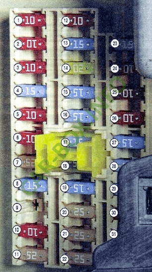
Fuse box

Located in the left end of the dashboard behind the protective cover.

General view of the interior Hyundai Elantra HD fuse box.
| Diagram | ||
|---|---|---|
|
||
| No. | Description | A |
| 1 | Starter relay - START | 10 |
| 2 | C control unit 10A - A / CON SW | 10 |
| 3 | Heated exterior mirrors - HTD MIRR | 10 |
| 4 | Heated Seat - SEAT HTR | 15 |
| 5 | Air Conditioning - A / CON | 10 |
| 6 | High beam lamps - HEAD LAMP | 10 |
| 7 | Windshield wiper - FR WIPER | 25 |
| 8 | Tailgate wiper - RR WIPER | 15 |
| 9 | Switching on the dipped beam during daytime - DRL OFF | 15 |
| 10 | Rear fog lamps - RR FOG | 10 |
| 11 | Control unit 25A lifts the glass - P / WDW LH | 25 |
| 12 | Clock - CLOCK | 10 |
| 13 | Cigarette lighter fuse - C / LIGHTER | 15 |
| 14 | Sunroof, ignition control unit relay - DR LOCK | 20 |
| 15 | Windshield heater relay - DEICER | 15 |
| 16 | Stop lights - STOP | 15 |
| 17 | Interior lighting - ROOM LP | 15 |
| 18 | Audio system, trip computer - AUDIO | 15 |
| 19 | Rear 5th door - T / LID | 15 |
| 20 | Power window lock (right side) - SAFETY P / WDW RH | 25 |
| 21 | Power window lock (left side) - SAFETY P / WDW LH | 25 |
| 22 | Power windows - P / WDW | 25 |
| 23 | power socket - P / OUTLET | 15 |
| 24 | Switch Block - T / SIG | 10 |
| 25 | Airbag Warning Lamp - A / BAG IND | 10 |
| 26 | Instrument panel - CLUSTER | 10 |
| 27 | Airbag - A / BAG | 15 |
| 28 | Door or ignition control unit - IGN1-A | 15 |
| 29 | Front Power Outlet - RR P / OUTLET | 15 |
| 30 | Rear right marker lamp - TAIL RH | 10 |
| 31 | Rear left marker lamp - TAIL RH | 10 |
Relay boxes
Additional relay modules are also located in the passenger compartment.
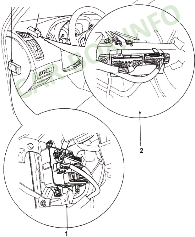
Description:
- 1 - rear light relay, power window relay, heater relay, tailgate relay;
- 2 - ICM Unit: Central locking relays, windshield defroster relay, rear fog light switch relay, horn relay, antitheft warning alarm relay, rain sensor relay.
