Table of Contents
The power circuits of the electrical equipment of the Japanese premium crossover are protected by fuses and relays. The elements are installed in distribution boxes located in the engine compartment and in the passenger compartment.

Considered fuse diagrams Infiniti EX25, EX35, EX37 2007, 2008, 2009, 2010, 2011, 2012, 2013 release.
In the engine compartment
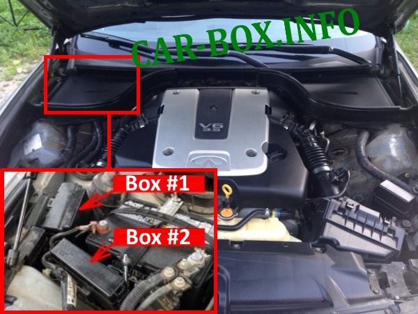
Fuse boxes located on the left side of the engine compartment.
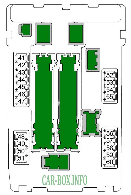
Fuse box #1
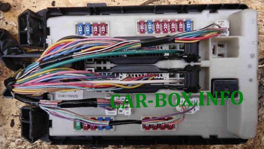
The photo shows an example.
| Diagram | ||
|---|---|---|
|
||
| No. | Description | A |
| 41 | Fuel module relay (fuel pump) | 15 |
| 42 | Engine cooling fan relay | 10 |
| 43 | Transmission Control Module (TCM) Snow Mode Switch | 10 |
| 44 | Injectors, engine control module (ECM), body electronics module (BCM) | 10 |
| 45 | ABS, Intelligent Cruise Control (ICC), Steering Angle Sensor, Power Steering Control Unit, 4WD, Yaw Rate Sensor | 10 |
| 46 | Oxygen sensors, air fuel ratio sensor | 15 |
| 47 | Multifunction switch (light switch) | 10 |
| 48 | Steering lock relay | 10 |
| 49 | Air conditioner relay | 10 |
| 50 | Engine control unit relay | 15 |
| 51 | Throttle valve relay | 15 |
| 52 | Front side light | 10 |
| 53 | Tail light, license plate light, VDC Off switch, adaptive headlight system (AFS), lane departure warning (LDW), multifunction switch (light switch), AV module, clock, glove box lighting, parking assist control unit , all-round vision system, seat heating switches, mirror control unit, overhead console (lamps), Snow mode switch | 10 |
| 54 | High beam left | 10 |
| 55 | High beam right | 10 |
| 56 | Low beam left | 15 |
| 57 | Low beam right | 15 |
| 58 | Front fog light relay | 15 |
| 59 | 10 | |
| 60 | Front wiper relay | 30 |
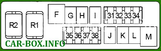
Fuse box #2

General view.
| Diagram | ||
|---|---|---|
|
||
| No. | Decoding of fuses | A |
| 31 | Horn relay, generator | 15 |
| 32 | Rear seat back control unit | 30 |
| 33 | Four-wheel drive | 10 |
| 34 | Audio system, AV module, iPo connector, surround view system, subwoofer, camera control unit, telephone, satellite radio receiver | 15 |
| 35 | Seat heating relay | 15 |
| 36 | Transmission control module (TCM) | 10 |
| 37 | - | - |
| 38 | Horn relay (2) | 15 |
| F | Engine cooling fan relay | 50 |
| G | Ignition relay (fuses: "2", "3", "4"), IPDM E / R (fuse box in the engine compartment # 1) | 30 |
| H | 40 | |
| I | - | - |
| J | - | - |
| K | Body Electronics Module (BCM), Circuit Breaker (Driver Settings Control Module, Power Driver Seat) | 40 |
| L | ABS | 30 |
| M | 50 | |
| Relay | ||
| R1 | Horn relay | |
| R2 | Gear selector lock | |
Power fuse panel
Located on the battery.
| Diagram | ||
|---|---|---|

|
||
| No. | Appointment | A |
| A | Alternator, fuses: "B", "C" | 140 |
| B | Fuses: "F", "G", "K", "L", "M", "31", "32", "33", "34", "35", "36", "38" | 100 |
| C | Ignition relay (fuses: "41", "42", "43", "44", "45", "46", "47"), fuses: "48", "49", "50", "51 " | 80 |
| D | High beam relay (fuses: "54", "55"), low beam relay (fuses: "56", "57"), side light relay (fuses: "52", "53"), fuses: "58" , "59", "60" | 60 |
| E | Auxiliary relay (fuses: "18", "19", "20"), rear window defogger relay (fuses: "13", "14", "15"), heater relay (fuses: "21", "22" ), fuses: "6", "7", "9", "10", "11" | 80 |
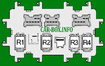
In the passenger compartment
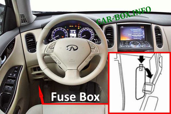
Located on the driver side.
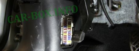
Access example.
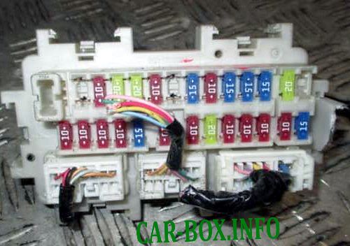
General view of the fuse box.
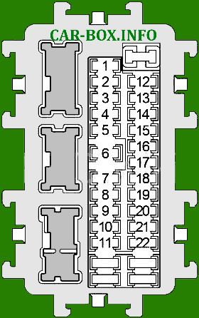
| Diagram | ||
|---|---|---|
|
||
| No. | Description | A |
| 1 | - | - |
| 2 | Airbags, passenger classification system | 10 |
| 3 | Headlight range control, gear selector lock relay, cruise control (ASCD / ICC), adaptive headlight system (AFS), diagnostic socket, lane departure warning (LDW), parking control unit, meter unit and air conditioning amplifier , seat heating relay, all-round vision system, buzzer, telephone, compressor, rearview mirror, AV module, lane departure warning system | 10 |
| 4 | Instrument cluster, reversing lamp relay | 10 |
| 5 | - | - |
| 6 | Key Slot, Keyless Access Warning Buzzer, Diagnostic Connector, A / C Meter and Amplifier, Rear Seat Back Control Module, Clock, Rearview Mirror | 10 |
| 7 | Brake Light Switch, Body Electronics Module (BCM), Cruise Control Relay (ICC Brake Hold Relay) | 10 |
| 8 | Amplifier BOSE | 20 |
| 9 | Start button, key slot | 10 |
| 10 | Seat memory, driver settings control unit, power mirrors, driver's seat control unit, body electronics module (BCM) | 10 |
| 11 | Instrument cluster | 10 |
| 12 | - | - |
| 13 | Heated mirrors | 10 |
| 14 | Heated rear window | 20 |
| 15 | 20 | |
| 16 | - | - |
| 17 | - | - |
| 18 | Front outlet / cigarette lighter fuse Infiniti EX25, EX35, EX37 | 15 |
| 19 | Instrument cluster, meter unit and air conditioning amplifier, display, multifunction switch, AV module, iPod connector, body electronics module (BCM), parktronic control unit, telephone, camera control unit, mirror control unit, satellite radio, surround view system | 10 |
| 20 | Socket - Console | 15 |
| 21 | Heater motor | 15 |
| 22 | Heater motor | 15 |
|
|
| No. | Relay |
| R1 | Ignition |
| R2 | Heated rear window |
| R3 | Auxiliary relay |
| R4 | Heater motor |
View and print PDF:
