The second generation of the Infiniti FX crossover, designed for the European market, was unveiled at the Geneva Motor Show in March 2008. The car went on sale in October 2008. At the end of 2013, in accordance with the company's new strategy, this crossover was renamed QX70.
In this article, we will take a detailed look at the fuse diagrams for the the Infiniti FX35 / FX37 / FX50 / QX70 1st generation (S51) 2008, 2009, 2010, 2011, 2012, 2013, 2014, 2015, 2016, 2017 release. Here are the locations and photos of the fuse and relay blocks. The fuse responsible for the “Cigarette lighter” is highlighted in bold.
In the engine compartment
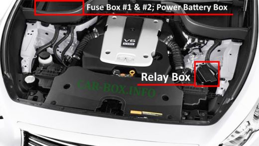
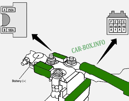
On the right side of the engine compartment, next to the battery, there are two fuse boxes and power fuses on the battery. An additional relay board is taken out separately.
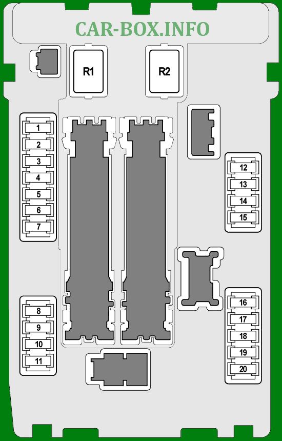
| Box #1 in the engine compartment (IPDM E / R) diagram |
|
| No. |
Description |
A |
| 1 |
Fuel module relay (fuel pump) |
15 |
| Fuel pump control unit |
| Fuel level sensor |
| Gasoline pump |
| Engine control unit (ECM) |
| 2 |
Cooling fan relay 2 |
10 |
| 3 |
Transmission control module (TCM) |
10 |
| Switch for "Snow" mode |
| 4 |
Injectors |
10 |
| Engine control unit (ECM) |
| Body Electronics Module (BCM) |
| Lighting control unit |
| 5 |
Intelligent Cruise Control (ICC) sensor |
10 |
| Gas pedal actuator |
| ABS electronic unit and actuator |
| Steering angle sensor |
| Yaw rate sensor |
| All-wheel drive control system |
| Power steering control unit |
| Rocker Restrictor Control Unit (RAS) |
| Intelligent Cruise Control (ICC) Buzzer |
| Brake booster control unit |
| 6 |
Heated Oxygen Sensor 2 (Bank 2) |
15 |
| Heated Oxygen Sensor 2 (Bank 1) |
| Air Fuel Ratio Sensor 1 (Bank 1) |
| Air Fuel Ratio Sensor 1 (Bank 2) |
| 7 |
Combination switch |
10 |
| 8 |
Not used |
- |
| 9 |
Air conditioner relay |
10 |
| Compressor |
| 10 |
Engine control unit relay |
15 |
| Engine control unit (ECM) |
| Capacitor |
| Intake Valve (Bank 1) |
| Intake Valve (Bank 2) |
| Exhaust Valve (Bank 1) |
| Exhaust Valve (Bank 2) |
| Canister valve (EVAP) |
| Ignition coils |
| MAF Sensor (Bank 2) |
| MAF Sensor (Bank 1) |
| Variable valve timing system (VVEL) |
| 11 |
Throttle valve |
15 |
| Engine control unit (ECM) |
| 12 |
Front side light |
10 |
| 13 |
Rear side light |
10 |
| License plate lighting |
| Glove box lighting |
| Lighting control unit |
| Front outlet (cigarette lighter) |
| ATT gear selector |
| AV module |
| 14 |
Left high beam |
10 |
| 15 |
Right high beam |
10 |
| 16 |
Left low beam |
15 |
| 17 |
Right low beam |
15 |
| 18 |
Front fog lights |
10 |
| 19 |
Not used |
- |
| 20 |
Wiper |
30 |
| Relay |
| R1 |
Not used |
| R2 |
Starter |
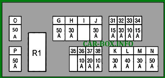
| Engine compartment fuse and relay diagram (box E12) |
|
| No. |
Decoding |
A |
| 31 |
Horn relay 1 |
15 |
| Generator |
| 32 |
Optional connector |
30 |
| 33 |
All-wheel drive control system |
10 |
| Brake booster control unit |
| 34 |
Front Monitor |
15 |
| AV module |
| Around View Monitor |
| Subwoofer |
| Satellite radio |
| Telephone adapter |
| 35 |
Not used |
- |
| 36 |
Transmission control module (TCM) |
10 |
| 37 |
Rocker Limiter Relay (RAS) |
20 |
| 38 |
Horn relay 2 |
10 |
| G |
Variable valve timing (VVEL) actuator relay |
50 |
| H |
Passenger compartment fuse box (J / B) |
30 |
| Engine compartment fuse box (IPDM E / R) |
| I |
Not used |
- |
| J |
Pre-crash seat belt pretensioner system (driver's side) |
30 |
| K |
Pre-crash belt tensioner system (passenger side) |
30 |
| L |
Body Electronics Module |
40 |
| Driver's seat adaptation system |
| Driver's seat control unit |
| M |
ABS electronic unit and actuator |
30 |
| N |
ABS electronic unit and actuator |
50 |
| O |
Cooling fan relay 1 |
50 |
| P |
Engine compartment fuse box (E213) - Fuse #Q, 61, 62, 63 |
50 |
| Relay |
| R1 |
Horn relay 1 |
| Battery-powered links |
|
| No. |
Appointment |
A |
| A |
Starter |
250 |
| Generator |
| Fuse #.: C. D, E |
| B |
Fuse #: O (Cooling fan relay 1), S (Cooling fan relay 2) |
100 |
| C |
Fuse box in the engine compartment (E12) |
100 |
| D |
Passenger compartment fuse box (J / B) (Fuse #: 5, 6, 7, 8, 9, 10, 11) |
80 |
| E |
Engine compartment fuse box (IPDM E / R) (Fuse no .: 10, 11) |
100 |
| F |
Engine compartment fuse box (IPDM E / R) (Fuse #: 18 (front fog lamp relay); high beam relay, low beam relay, side light relay) |
60 |
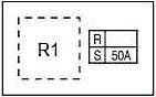
| Engine compartment relay box (type E212; VK motors) |
|
|
| No. |
Appointment |
A |
| R |
Not used |
- |
| S |
Cooling fan relay 2 |
50 |
| Relay |
| R1 |
Cooling fan relay 2 |
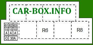
| Relay box (type E213) |
|
| No. |
Description |
A |
| 61 |
Gas pedal actuator |
15 |
| 62 |
Seat climate control relay |
15 |
| 63 |
Seat climate control relay |
10 |
| Seat heating relay |
| Q |
Automatic tailgate |
30 |
| Relay |
| R6 |
Horn relay 2 |
| R8 |
Brake Lock Relay (Intelligent Cruise Control (ICC)) |
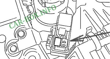
In the passenger compartment
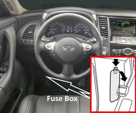
Located at the driver's feet, on the left-hand side, behind the protective cover.
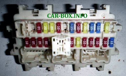
General view of fuse box.
| Diagram (J / B) |

|
| No. |
Appointment |
A |
| 1 |
Not used |
- |
| 2 |
Seat occupied recognition system |
10 |
| Airbags |
| 3 |
Front right combination lamp |
10 |
| Front left combination lamp |
| Ionizer |
| Seat climate control relay |
| Block "Unified Meter And A / C Amp." |
| Tire pressure monitoring system |
| Multiplex Bus Controller |
| AV module |
| Exhaust gas sensor |
| Auto dimming rearview mirror |
| Brake Lock Relay (Intelligent Cruise Control (ICC)) |
| ASCD switch |
| Stop lamp switch |
| Adaptive road lighting system (AFS) |
| Diagnostic connector |
| Alarm switch |
| Lane Keeping Camera Buzzer |
| Lane tracking camera |
| Compressor |
| Telephone adapter |
| Seat heating relay |
| Seat heating switch (driver's side) |
| Seat heating switch (passenger side) |
| 4 |
Instrument cluster |
10 |
| Reversing lamp relay |
| Around View Monitor |
| Sonar |
| 5 |
Auxiliary relay |
20 |
| 6 |
Key connector |
10 |
| Watch |
| Diagnostic connector |
| Rain sensor |
| Key buzzer |
| Auto dimming rearview mirror |
| 7 |
Brake Lock Relay (Intelligent Cruise Control (ICC)) |
10 |
| Stop lamp switch |
| Body Electronics Module (BCM) |
| 8 |
Bose (audio system) |
20 |
| 9 |
Key connector |
10 |
| Start button |
| 10 |
Body Electronics Module (BCM) |
10 |
| Driver's seat adaptation system |
| Lighting control unit |
| Seat memory switch |
| Driver's seat control unit |
| 11 |
Instrument cluster |
10 |
| Block "Unified Meter And A / C Amp." |
| All-wheel drive control system |
| Multiplex Bus Controller |
| Pre-crash seat belt pretensioner system |
| 12 |
Spare fuse |
- |
| 13 |
- |
| 14 |
No |
- |
| 15 |
Power mirrors |
10 |
| 16 |
Heated rear window |
20 |
| 17 |
Heated rear window |
20 |
| 18 |
E-SUS |
10 |
| 19 |
Not used |
- |
| 20 |
Front outlet (infinity fx cigarette lighter) |
15 |
| 21 |
Mirror control unit |
10 |
| Block "Unified Meter And A / C Amp." |
| Multifunctional switch |
| Lighting control unit |
| AV module |
| Around View Monitor |
| Telephone adapter |
| Satellite radio |
| 22 |
Console socket |
20 |
| Rear socket |
| 23 |
Heater motor |
15 |
| 24 |
15 |
| 25 |
Spare fuse |
- |
| 26 |
- |
| Relay |
| R1 |
Ignition relay |
| R2 |
Heated rear window relay |
| R3 |
Auxiliary relay |
| R4 |
Heater relay |
