The Infiniti FX crossover is the original premium urban all-wheel drive vehicle with off-road properties. In the US, the Infiniti FX was introduced back in 2002. All FX variants are based on a redesigned FM (Front Mid-ship) architecture platform, which features an engine positioned behind the front axle. The result is an optimal weight distribution between the front and rear axles. This factor affects the movement of the car during such basic maneuvers as entering and exiting corners, which is of great importance for a crossover.

In this article, we will take a detailed look at the fuse diagrams for the the Infiniti FX35 / FX45 1st generation (S50) 2002, 2003, 2004, 2005, 2006, 2007, 2008, 2009 release. Here are the locations and photos of the fuse and relay blocks. The fuse responsible for the “Cigarette lighter” is highlighted in bold.
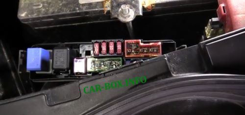
In the engine compartment
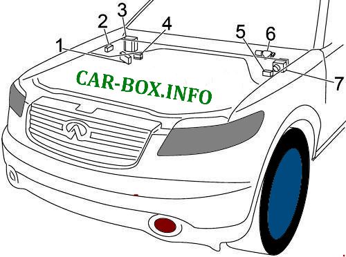
Location of components:
1. Fuse box # 2,
2. Relay box # 1,
3. Fuse box # 1 (IPDM),
4. Power fuse box,
5. '06 -'08: Relay box # 2,
6. Wiper motor,
7. ABS control unit
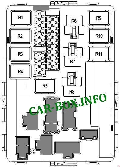
Fuse box #1
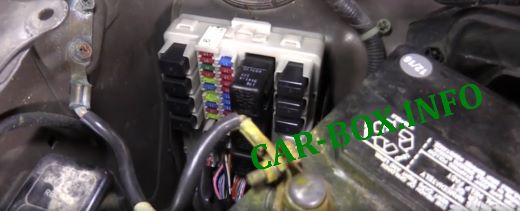
Located behind the trim. For access you need to remove it.
General view.
| Diagram | ||
|---|---|---|
|
||
| No. | Description | A |
| 71 | Side light, headlight range control unit, tail lamp control unit, license plate light, glove box light, instrument panel light | 10 |
| 72 | Right headlight (high beam | 10 |
| 73 | Front wiper relay | 30 |
| 74 | Left headlight (high beam) | 10 |
| 75 | Heated rear window relay | 20 |
| 76 | Right headlight (low beam) | 15 |
| 77 | Engine control unit (ECM), ECM relay, MAF sensor, crankshaft position sensor, camshaft position sensors, ignition coils, EVAP valve, variable valve timing | 20 |
| 78 | Heated wipers area | 15 |
| 79 | A / C Compressor Clutch | 10 |
| 80 | Heated rear window relay, fuse: "8" | 20 |
| 81 | Fuel pump relay, engine control module (ECM) | 15 |
| 82 | ABS | 10 |
| 83 | Transmission control module (TCM), reverse lamp relay. display, navigation. Rear View Camera | 10 |
| 84 | Front and rear washer | 10 |
| 85 | Oxygen sensors, air / fuel ratio sensors | 10 |
| 86 | Left headlight (low beam) | 15 |
| 87 | Throttle valve relay, engine control module (ECM) | 15 |
| 88 | Front fog light relay | 15 |
| 89 | Diagnostic connector, EVAP valve, intake manifold geometry change system (VIAS (VK45DE)) | 10 |
| Relay | ||
| R1 | The engine control unit | |
| R2 | High beam | |
| R3 | Low beam | |
| R4 | Starter | |
| R5 | Ignition | |
| R6 | Cooling fan (no. 3) | |
| R7 | Cooling fan (no. 1) | |
| R8 | Cooling fan (No. 2) | |
| R9 | Throttle valve | |
| R10 | Fuel module (fuel pump relay) | |
| R11 | Front fog light | |
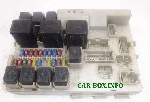
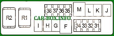
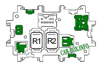
Fuse box #2
Located near the battery.

General view.
| Diagram | ||
|---|---|---|
|
||
| No. | Decoding | A |
| 31 | External trailer lighting | 30 |
| 32 | Audio, subwoofer, display, climate control and multimedia control unit, navigation, DVD player, telephone | 15 |
| 33 | Generator | 10 |
| 34 | Horn relay | 15 |
| 35 | Intelligent Cruise Control (ICC) | 10 |
| 36 | Daytime Running Lights | 10 |
| 37 | Transmission control module (TCM) | 10 |
| 38 | Smart key control unit, steering wheel lock, ignition switch | 10 |
| F | Ignition switch, starter relay | 40 |
| G | Cooling fan relay # 1, cooling fan relay # 3 | 40 |
| H | Cooling fan relay # 2 | 40 |
| I | ABS | 50 |
| J | - | - |
| K | Auxiliary relay # 2 (Fuses: "2", "3") | 30 |
| L | ABS | 30 |
| M | Body electronics module (BCM), driver's seat adaptation control module, power seats, power windows, rear wiper, sunroof, interior lighting, turn signals and hazard warning lights | 50 |
| Relay | ||
| R1 | Horn relay | |
| R2 | Auxiliary relay # 2 | |
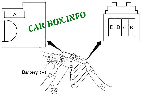
Power fuse panel
Located on the battery.
| Diagram | ||
|---|---|---|
|
||
| No. | Appointment | A |
| A | Alternator, fuses: "B", "C" | 120 |
| B | Fuses: "32", "33", "34", "35", "36", "37", "38", "F", "G", "H", "I", "K", "L", "M" | 100 |
| C | High beam relay (fuses: "72", "74"), low beam relay (fuses: "76", "86"), fuses: "71", "73", "75", "87", "88 " | 80 |
| D | Auxiliary relay (fuses: "4", "6", "7"), heater relay (fuses: "10", "11"), fuses: "17", "18", "19", "20", "21", "22" | 60 |
| E | Ignition relay (air conditioning relay, front wiper relay, wiper speed relay, fuses: "81", "82", "83", "84", "85", "89"), fuses: "77", "78" , "79", "80" | 80 |
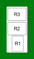
Relay box #1
#2 on the picture.
| Diagram | |
|---|---|
|
|
| No. | Relay |
| R1 | Daytime Running Lights |
| R2 | Intelligent Cruise Control (ICC) |
| R3 | Heated rear window |
Relay box #2
#5 on the picture.
| Diagram | |
|---|---|

|
|
| No. | Relay |
| R1 | Reversing lamps |
| R2 | - |
In the passenger compartment
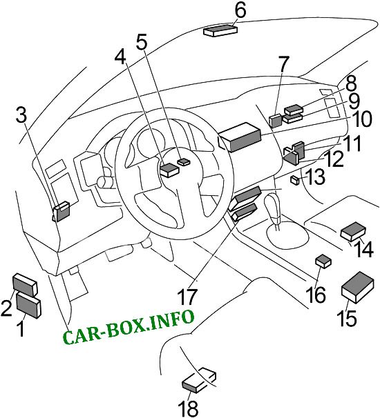
Component Locations: 1. Body Electronics Module (BCM), 2. Fuse Box (the unit is located at the driver's feet on the left side, behind a plastic cover), 3. Smart Key Control Module, 4. Steering Lock Box, 5. Immobilizer Antenna Amplifier, 6. Lane Keeping Assist (LDW) Camera Control Module, 7. Tire Pressure Monitoring System Control Unit, 8. TEL Adapter Unit, 9. Display Control Unit, 10. Unified Meter And A / C Amp. Unit, 11. Intelligent Cruise Control (ICC) Control Unit, 12. Unit engine control module (ECM), 13. All-wheel drive control unit, 14. Driver's seat adaptation control unit, 15. Navigation control unit, 16. Airbag control unit, 17. Rear camera control unit, 18. Driver's seat control unit.
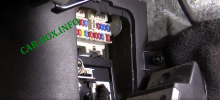
Access example. The plastic cover is removed.
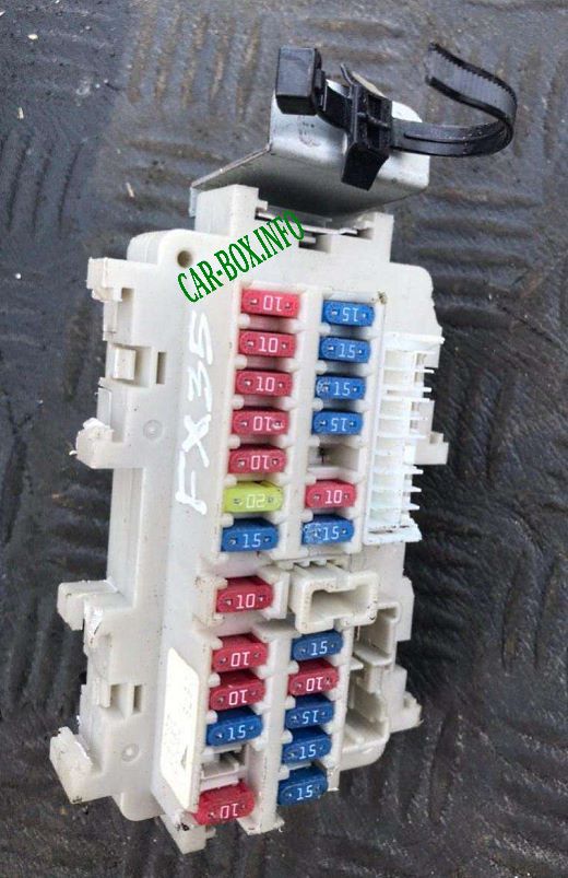
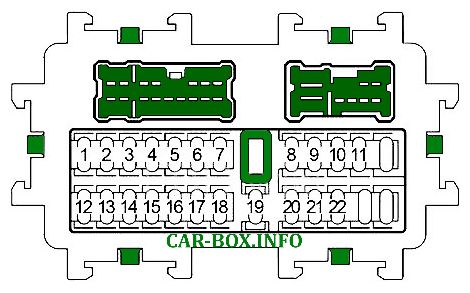
General view.
| Diagram | ||
|---|---|---|
|
||
| No. | Description | A |
| 1 | Body Electronics Module (BCM), Engine Control Module (ECM), Injectors | 15 |
| 2 | Luggage compartment socket | 15 |
| 3 | Rear socket | 15 |
| 4 |
|
15 |
| 5 | - | - |
| 6 | Audio, display, satellite radio, "Unified Meter And A / C Amp." Unit, antenna amplifier, body electronics unit (BCM), rear camera, navigation, climate and multimedia control unit, smart key, DVD player, telephone , instrument cluster, external smart key antenna | 10 |
| 7 |
|
15 |
| 8 | Heated mirrors | 15 |
| 9 | Instrument cluster, driver's seat adaptation control unit | 10 |
| 10 | Heater motor block "Unified Meter And A / C Amp." | 15 |
| 11 | Heater motor block "Unified Meter And A / C Amp." | 15 |
| 12 | Intelligent cruise control, engine control unit, "Unified Meter And A / C Amp." Block, brake light switch, automatic transmission lever lock solenoid, air conditioning compressor, display, navigation, telephone, smart key, steering angle sensor, snow mode, lane keeping system (LDW), electrochromic rear mirror (compass), heated rear window relay, four-wheel drive, ASCD switch | 10 |
| 13 | Airbags | 10 |
| 14 | Instrument cluster | 10 |
| 15 | Heated seats | 10 |
| 16 | '02 -'05: Oxygen sensors, air / fuel ratio sensors | 10 |
| 17 | Audio amplifier (BOSE) | 20 |
| 18 | Trunk lid control unit | 15 |
| 19 | Instrument cluster, "Unified Meter And A / C Amp." Block, diagnostic connector, rear camera, anti-theft indicator, clock | 10 |
| 20 | Brake Light Switch, Intelligent Cruise Control, ABS, "Unified Meter And A / C Amp.", Tail Lamp Control Module | 10 |
| 21 | Four-wheel drive | 10 |
| 22 | Body electronics module (BCM), lock ignition, immobilizer antenna amplifier, driver's seat adaptation control unit | 15 |
| Relay | ||
|
||
| R1 | Heater | |
| R2 | Subsidiary | |
Car body
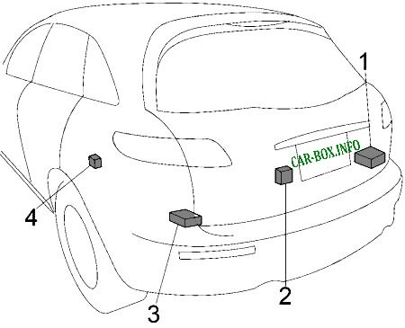
Component locations: 1. Audio amplifier (BOSE), 2. Trunk lid control unit, 3. Rear lamp control unit, 4. '03 -'05: Reversing lamp relay

Need help finding 2007 FQ35 fuel pump relay location.
Where do I purchase the fuel pump relay part# 33201 M15.