The Rio is a subcompact car produced by Kia since November 1999. Body styles include a three- and five-door hatchback and a four-door sedan, powered by inline four-cylinder gasoline and diesel engines. In this article, we will take a detailed look at the fuse box diagrams for the Kia Rio (second generation; JB index) 2006, 2007, 2008, 2009, 2010, 2011 years of manufacture.

Here you will find the locations and photos of distribution boxes. The fuses responsible for the “Cigarette lighter” and “Fuel Pump” are highlighted in bold.
In the engine compartment
Depending on the engine fitted to the vehicle (petrol or diesel) there may be one or two units here.
Main fuse box
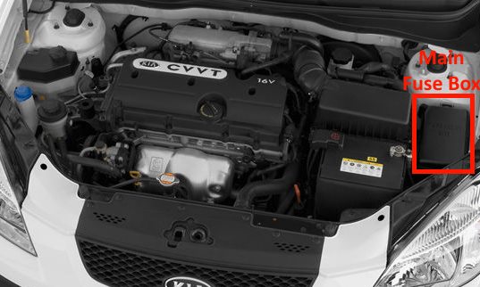
Located on the left side of the underhood. Remove the protective cover to access it.
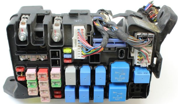
General view.
| Diagram | ||
|---|---|---|

|
||
| № | Amp rating / Description | Amps |
| 1 | MDPS Electric Power Steering | 80 |
| 2 | Alternator | 125 / 150 |
| 3 | ECUB - Engine Control Unit | 10 |
| 4 | ECUD - Engine Control Unit | 10 |
| 5 | HORN - Beep (sound signal) | 10 |
| 6 | IGN1 - Ignition switch (lock) | 30 |
| 7 | IGN2 - Starter, ignition switch (lock) | 40 |
| 8 | BATT2 - Generator, battery | 30 |
| 9 | BATT1 - Generator, battery | 50 |
| 10 | ECUA - Engine control unit | 30 |
| 11 | RAD - radiator fan | 30 |
| 12 | COND - condenser fan | 30 |
| 13 | ABS1 - ESP and anti-lock brakes system | 40 |
| 14 | ABS2 - ESP and anti-lock brakes system | 40 |
| 15 | P / WDW - power windows | 30 |
| 16 | BLOWER - radiator fan relay | 40 |
| 17 | A / CON 1 - Air conditioner | 10 |
| 18 | A / CON 2 - Air conditioner | 10 |
| 19 | ECUC - Engine Control Unit | 20 |
| 20 | INJ - Fuel Injectors, air conditioning system | 15 |
| 21 | SNSR - Sensors | 10 |
| № | Relay assignment | |
| R1 | condenser fan relay (low speed) | |
| R2 | Radiator fan relay | |
| R3 | Fuel pump relay | |
| R4 | Main relay | |
| R5 | Horn relay | |
| R6 | Fuel filter heater relay | |
| R7 | Heater blower motor relay | |
| R8 | Starter relay | |
| R9 | condenser fan relay (high speed) | |
| R10 | Air conditioning relay | |
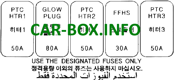
Additional distribution box
Installed in diesel engine models.
|
|
| Legend | Amps |
| Heater PTC 1 | 50 |
| Glow plug | 80 |
| Heater PTC 2 | 50 |
| Fuel filter heating | 30 |
| Heater PTC 3 | 50 |
In the passenger compartment

It is located on the driver's side of the dashboard. Remove the plastic cover to gain access.

General view of the KIA Rio 2 interior fuse box.
| Diagram | ||
|---|---|---|

|
||
| № | Legend | A |
| 1 | RR WIPER - Rear tailgate wiper | 15 |
| 2 | H / LP- Left headlamp bulbs | 10 |
| 3 | FR WIPER - Front windshield wiper | 25 |
| 4 | BLOWER - Fan | 10 |
| 5 | H / LP (RH) - Right headlamp bulbs | 10 |
| 6 | S / ROOF - Sunroof | 20 |
| 7 | STOP LP - Stop lamps | 15 |
| 8 | C / DR LOCK - Central door lock switch | 20 |
| 9 | IGN COIL - Ignition Coil | 15 |
| 10 | ABS - Anti Lock Brake System | 10 |
| 11 | B / UPLP - Reversing lamps | 10 |
| 12 | BMS - Reserve | - |
| 13 | Kia Rio 2 cigarette lighter fuse | 25 |
| 14 | FOLD'G - Folding drive for exterior mirrors | 10 |
| 15 | HTR SEAT - Heated Seat | 20 |
| 16 | AMP - Amplifier | 25 |
| 17 | FR FOG LP - Front Fog Lamps | 10 |
| 18 | DRL - Daytime Running Lights | 10 |
| 19 | ECU - Engine management system | 10 |
| 20 | CLUSTER - Instrument panel | 10 |
| 21 | P / WDW RH - Locking power windows (right side) | 25 |
| 22 | Audio system, trip computer | 10 |
| 23 | Rear fog lamp - RR FOG LP | 10 |
| 24 | IGN Switch (ignition switch) | 10 |
| 25 | Heated rear window - HTD GLASS | 30 |
| 26 | A / BAG - Safety Airbags | 15 |
| 27 | Automatic transmission control unit - TCU | 10 |
| 28 | Sensors - SNSR | 10 |
| 29 | SPARE | - |
| 30 | MULT B / UP - Air conditioning control unit, clock, interior lighting, ETACS | 10 |
| 31 | Audio system | 15 |
| 32 | P / WDW LH - Power window locking (left side) | 25 |
| 33 | HTD MIRR - Heated exterior mirrors | 10 |
| 34 | TAIL LP (LH) - Left rear side lamp | 10 |
| 35 | TAIL LP (RH) - Right tail lamp | 10 |
| 36 | HAZARD - Alarm | 10 |
| 37 | T / SIG LP - Turn Signal Lamps | 10 |
| 38 | A / BAG IND - Airbag warning lamp | 10 |
| 39 | START - Red Starter relay | 10 |

Some relay modules are located on the rear panel of the unit: anti-theft alarm and direction indicators, buzzer, etc.

In sedans, a separate brake light relay is located in the rear, near the rear signal control box.

the passenger compartment fuse box does not match mine as i only have 9 fuses on top row the 3rd fuse is not the FR WIPER - Front windshield wiper as i took this out and the wiper still worked