The Rio is a subcompact car produced by Kia since November 1999. Body styles include a three- and five-door hatchback and a four-door sedan, powered by inline four-cylinder gasoline and diesel engines. In this article, we will take a detailed look at the fuse box diagrams for the Kia Rio (third generation; UB / QB index) 2011, 2012, 2013, 2014, 2015 and 2016 years of manufacture.

Here you will find the locations and photos of distribution boxes. The fuses responsible for the “Cigarette lighter” and “Fuel Pump” are highlighted in bold.
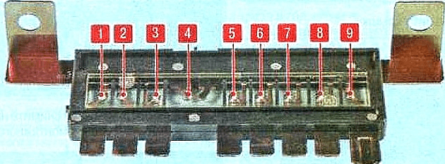
In the engine compartment

Located behind the plastic cover on the left side.
Type 1

Example of a schematic from the block cover.
| Diagram | ||
|---|---|---|

|
||
| № | Legend | A |
| F1 | Spare | - |
| F2 | Heated exterior mirror relay | 10 |
| F3 | Kia Rio 3 fuel pump fuse | 15 |
| F4 | Horn | 10 |
| F5 | Air conditioner | 10 |
| F6 | Spare | - |
| F7 | Spare | - |
| F8 | Power system (fuel injectors), engine control unit, variable valve timing solenoid valve | 15 |
| F9 | Engine management system sensors, engine control unit, immobilizer module | 10 |
| F10 | Block TSM | 10 |
| F11 | Reversing lamps | 10 |
| F12 | Spare | - |
| F13 | Spare | - |
| FL1 | Instrument panel junction box | 50 |
| FL2 | Engine cooling fan relay (high, low speed) | 30 |
| FL3 | engine control unit | 30 |
| FL4 | Electronic key system control unit relay, ignition switch (without electronic key system) | 40 |
| FL5 | Engine start relay (electronic key system), ignition switch (without electronic key system) | 50 |
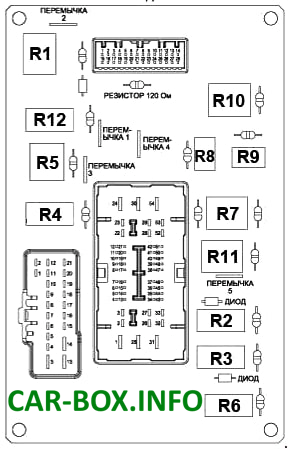
| R1 | Spare | |
| R2 | Emergency brake warning relay | |
| R3 | Fuel pump relay | |
| R4 | Heated exterior rear view mirror relay | |
| R5 | Horn relay | |
| R6 | Air conditioner relay | |
| R7 | Fan relay (low speed) | |
| R8 | Spare | |
| R9 | electronic motor control unit relay | |
| R10 | Relay for the electric heater blower fan | |
| R11 | Spare | |
| R12 | Ignition lock relay | |
| R13 | Fan relay (high speed) | |
| R14 | Spare | |
| Some relay modules may be located on the back of the unit: horn relay, horn relay, starter relay, etc. | ||
The power fuse panel is located on the left side of the main unit.
|
||
| № | Legend | A |
| 1 | Instrument Panel Junction Box, Taillight Relay | 50 |
| 2 | Spare | - |
| 3 | Spare | - |
| 4 | Generator | 125 |
| 5 | ABS module, diagnostic connector | 40 |
| 6 | ABS Module | 40 |
| 7 | Rear window defogger relay | 40 |
| 8 | Relay for the electric heater fan | 40 |
| 9 | Spare | - |
Type 2

General view.

Example of a schematic from the block cover.
| Diagram | ||
|---|---|---|

|
||
| Name | Description | A |
| MDPS | electronic power steering control module | 80 |
| ALT | Alternator | 125 |
| B+1 | I/P Junction Box (Power Connector Fuse : ROOM LP 10A / AUDIO 20A, Fuse : FOG LP FRT 15A / MODULE 1 10A / STOP LP 15A, Tail Lamp Relay) | 50 |
| INVERTER | Inverter | 40 |
| B+2 | I/P Junction Box (Fuse : HAZARD 15A / PDM 1 25A / PDM 2 10A / SUNROOF 15A / DR LOCK 20A / SAFETY POWER WINDOW 25A / S/HEATER 2 15A, FOLD'G MIRR 10A / Power Window Relay) | 50 |
| IG1 |
|
40 |
| ABS1 | Electronic Stability Control Module, Multipurpose Check Connector | 40 |
| ABS2 | Electronic Stability Control Module | 40 |
| RR HTD | I/P Junction Box (Rear Defogger Relay) | 40 |
| ECU 5 | PCM | 10 |
| H/LP HI IND | Instrument Cluster | 10 |
| IG2 | PCB Fuse & Relay Box (Start Relay), W/O Smart Key - Ignition Switch, With Smart Key - PDM Relay Box (ESCL (IG2) Relay) | 40 |
| ECU1 | PCB Fuse & Relay Box (Engine Control Relay, ECU2 10A) | 30 |
| ECU3 | Spare | 10 |
| BLOWER | Blower Relay | 40 |
| C/FAN | Cooling Fan (Low) Relay, Cooling Fan (Hi) Relay | 40 |
| F/PUMP | Fuel Pump #1 Relay | 20 |
| H/LAMP HI | HeadLamp (HI) Relay | 20 |
| H/LAMP | Head Lamp (LO) Relay | 20 |
| HORN | Horn Relay, Burglar Alarm Horn Relay | 10 |
| ECU2 | M/T - ECM, ATT - E/R Junction Box (ECU_VM 10A) | 10 |
| B/UP LAMP | A/T - PCM, Transmission range selector switch | 10 |
| WIPER | ECM/PCM, Rain Sensor | 10 |
| ECU4 | ECM/PCM | 20 |
| INJECTOR | ECM/PCM, PCB Fuse & Relay Box (Fuel Pump #1 Relay) | 15 |
| H/LAMP LH | Headlamp Left Side | 10 |
| SENSOR1 | Purge control solenoid valve, variable inlet solenoid valve, canister closure valve, PCB fuse box and relays (cooling fan relay (low), cooling fan relay (high)) | 10 |
| SENSOR2 | Oil Control Valve #1/#2, Oxygen Sensor (Up/Down) | 10 |
| H/LAMP RH | Headlamp Right Side | 10 |
In the passenger compartment

It is located on the driver's side under the dashboard.

General view of the KIA Rio 3 interior fuse box.
| Diagram | ||
|---|---|---|

|
||
| № | Description | A |
| 1 | Windshield wiper rest area heater relay | 15 |
| 2 | P / OUTLET - Socket for connection of additional equipment | 15 |
| 3 | Kia Rio 3 cigarette lighter fuse | 15 |
| 4 | Front directional light bulb, power outside mirrors, BCM, current converter, electronic key ECU, audio system, digital clock, head unit with navigation | 10 |
| 5 | A / BAG IND - Front airbag deactivation warning light | 10 |
| 6 | A / BAG - SRS safety system control unit | 10 |
| 7 | Alarm switch | 10 |
| 8 | MOPS 2 ECU EUR | 10 |
| 9 | Spare | - |
| 10 | Rear window wiper and washer (optional) | 15 |
| 11 | Steering wheel heater | 15 |
| 12 | Rear fog lamp relay | 10 |
| 13 | Front fog lamp relay | 15 |
| 14 | ROOM 2 - Automatic light switch-off relay (door sensor), automatic transmission gear lever engagement | 10 |
| 15 | STOP LP - Relay, brake light switch, electronic key system control unit, electronic key ECU, relay US, data connector | 15 |
| 16 | CLUSTER - instrument cluster, BCM unit, audio system, automatic transmission shift lever illumination, tire pressure monitoring module | 10 |
| 17 | IGN 1 - Brake light switch, seat heating, diagnostic socket, parking sensors | 10 |
| 18 | ABS Front Panel Switch, ESC Module, HAC Relay | 10 |
| 19 | B / UP LP - Reversing light switch | 10 |
| 20 | PCU - Engine control unit, electronic key system control unit, speed sensor, brake light switch, inverter, A / C ECU | 10 |
| 21 | H / LP LH - Left headlamp | 10 |
| 22 | Daytime running lights | 10 |
| 23 | HAZARD - Alarm relay, ВСМ | 15 |
| 24 | SMK_1 - Electronic key control unit | 25 |
| 25 | Sunroof motor | 15 |
| 26 | SMK_2 - Engine start and stop button | 10 |
| 27 | PCU - Vehicle speed sensor (manual gearbox), transmission mode switch (automatic gearbox) | 15 |
| 28 | IGN COIL - Ignition coils, capacitor | 15 |
| 29 | IGN - Daytime running lights, high beam control unit, air conditioning control unit, headlights, power window relay (without BCM), BCM unit, electronic key system control unit (with BCM unit) | 10 |
| 30 | Windshield wiper, steering column switch | 25 |
| 31 | DOOR LOCK - Relay for door lock control unit (with BCM unit), driver's door lock drive (without BCM unit) | 20 |
| 32 | SAFETY P / WDW - Safety power windows | 25 |
| 33 | S / HEATER - Heated front seats | 15 |
| 34 | Exterior mirrors adjuster, electric | 10 |
| 35 | ROOM 1 - Interior lighting, trunk lighting, air conditioning, tire pressure monitoring module, digital clock | 10 |
| 36 | AUDIOС ISG: converter, Without ISG: audio system, head unit with navigation | 20 |
| 37 | TAIL LH - Rear left lamp, license plate lamps, left block - headlight, instrument panel illumination | 10 |
| 38 | TAIL RH - Right tail light, right headlight unit, instrument panel illumination | 10 |
| 39 | START - Ignition lock switch (MKP), transmission mode switch (AKP) | 10 |
| 40 | H / LP RH - Right headlamps, instrument cluster | |
| 41 | P / WDW LH - power window control unit, left rear power window switch | 25 |
| 42 | P / WDW RH - power window control unit, right rear power window switch | 25 |
| 43 | RR HTD - Heated exterior mirror system, ECM / RSMB Air Conditioning ECU | 10 |
| 44 | A / CON 2 - Air conditioner | 10 |
| 45 | Spare | - |
| Non-removable relays are attached to the back of the block. | ||
|
||
| № | Decoding | |
| R1 | Rear window heater relay | |
| R2 | Fog lamp relay | |
| R3 | Relay for rear fog lamps | |
| R4 | Side lamp relay | |
| R5 | Daytime running lamps relay | |
| R6 | Windscreen defroster relay | |
| R7 | Door lock relay | |
| R8 | Trunk lid opener relay | |
| R9 | Direction indicator relay | |
| R10 | Alarm relay | |
| R11 | Power window relay | |
| R12 | Burglar alarm relay | |
