Soul is a mini-SUV by Kia Motors. The production model was first presented at the Paris Motor Show in the fall of 2008. In the model range, the car is located between the cee'd and Sportage. In this article, we will take a detailed look at the fuse box diagrams for the Kia Soul (first generation; AM index) 2008, 2009, 2010, 2011, 2012, 2013, 2014 years of manufacture.

Here you will find the locations and photos of distribution boxes. The fuses responsible for the “Cigarette lighter” and “Fuel Pump” are highlighted in bold.
In the engine compartment
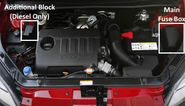
Location of components.
Primary fuse box
This unit may be available in several versions.
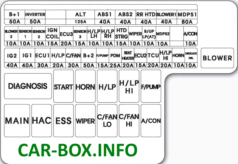
Type 1

General view.
| Diagram | ||
|---|---|---|
|
||
| Name | Legend | A |
| B + 1 | Junction box I / P (glass lifter relay, fuses - P / WDW LH 25A, P / WDW RH 25A, PDM 2 10A, DANGER 15A) | 50 |
| INVERTER | Oil Pump Inverter | 50 |
| ALT | Alternator, fuse (ABS 2 40A, ABS 1 40A, RR HTD 40A, BLOWER1 40A, MDPS 80A, A / CON 10A) | 125 |
| ABS 1 | ESC Module | 40 |
| ABS 2 | ESC Module | 40 |
| RR HTD | Junction Box I / P (Rear Heating Relay) | 40 |
| BLOWER 1 | Fan relay | 40 |
| MDPS 1 | EPS control module | 80 |
| IG 2 | Ignition Switch, PDM Relay Box (IG 1 Realy), Start Relay | 40 |
| IG 1 | Ignition Switch, PDM Relay Box (IG 2 Realy) | 40 |
| ECU 1 | Engine control relay | 30 |
| H / LP | Headlight relay | 20 |
| C / FAN | A / C fan relay | 30 |
| B + 2 | I / P Junction Box (Tail Light Relay, Fuse - TAIL LP LH 10A, TAIL LP RH 10A, SUNROOF 20A, AMP 25A, DR LOCK 20A, STOP LP 15A, T / GATE OPEN 15A, (FOG LP FRT) 15A, power supply Connector - ROOM LP 10A, MODULE 15A) | 50 |
| F / PUMP | Kia Soul fuel pump fuse | 15 |
| PDM | PDM, Smart Key Control Module | 25 |
| SEAT HEATER | Heated driver's seats, Heated passenger seats | 20 |
| ECU 2 | PCM / ECM | 15 |
| TCU | PCM | 20 |
| H / LP HI | Headlight relay | 20 |
| HORN | Sound Signal relay (beep) | 10 |
| DEDICATE DRL | BCM | 10 |
| BLOWER 2 | Air conditioning control module (Auto) | 10 |
| SENSOR 1 | Camshaft position sensor # 1 / # 2, oil control valve # 1 / # 2, canister control valve, air conditioning relay, immobilizer module | 10 |
| SENSOR 2 | C / Fan Hl / Low Relay, Injector # 1 - # 4 | 10 |
| IGN COIL | Ignition coil # 1 ~ # 4, capacitor | 15 |
| ECU 3 | PCM / ECM | 20 |
| SENSOR 3 | Oxygen Sensor (Up / Down), Fuel Pump Relay, Purge Control Solenoid, Variable Air Flow Solenoid | 15 |
| H / LP LH | Left headlight | 10 |
| H / LP RH | Right headlight | 10 |
| HTD STRG | Heated steering wheel | 15 |
| WIPER | PCM | 10 |
| B / UP LP (AP) | Electro chrome mirror, left / right side combination rear light, instrument cluster, A / V and navigation head unit, audio | 10 |
| MDPS2 | EPS control module | 10 |
| A / CON | A / C compressor relay | 10 |
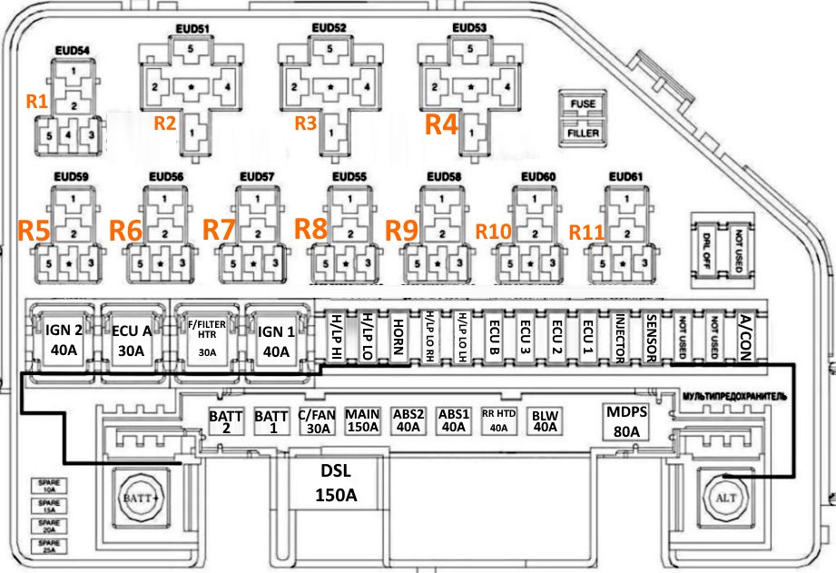
Type 2
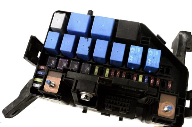
General view.
| Diagram | ||
|---|---|---|
|
||
| Name | Description | A |
| BATT 2 | Junction box l / P (relay - taillights, fuses -TAIL LH 10A.TAIL RH 10A, S / ROOF 20A, AMP 25A, DR LOCK 20A, STOP 15A, T / GATE 15A, F / FOG 15A, R / FOG 10A, power connectors - ROOM 10A, AUDIO 15A) | 50 |
| BATT 1 | Junction box l / P (relay - glass servo, fuses - P / WDW LH 25A, P / WDW RH 25A, FOLD'G 10A, HAZARD 15A) | 50 |
| C / FAN | Compressor fan relay (upper), compressor fan relay (lower) | 30 |
| MAIN | Alternator, fuses (ABS 2 40A, ABS 1 40A, RR NTO 40A, BLW 40A, MDPS 80A, A / CON 10A, DSL 150A) | 150 |
| ABS 2 | ABS control module, ESP control module | 40 |
| ABS 1 | ABS control module, ESP control module | 40 |
| RRHTD | Junction box I / P (rear window defogger relay) | 40 |
| BLW | Fan relay | 40 |
| MDPS | electronic power steering control module | 80 |
| DSL | DSL relay and fuse box (GLOW 80A, PTC 1 50A, PTC 2 50A, PTC 3 50A) | 150 |
| IGN 2 | Ignition switch, starting relay | 40 |
| ECU A | Main relay, ECU B10A | 30 |
| F / PUMP | G4FC: Fuel pump relay | 20 |
| F / FILTER HTR | D4FB: Fuel filter heater relay | 30 |
| IGN 1 | ignition switch | 40 |
| H / LP HI | Headlight relay (high beam) | 20 |
| H / LP LO | Headlight relay (low beam) | 20 |
| HORN | Horn relay | 10 |
| HORN | Horn relay | 10 |
| H / LP LO RH | Right headlight | 10 |
| H / LP LO LH | Left front headlight, dashboard (low beam indicator) | 10 |
| ECU B |
|
10 |
| ECU 3 | D4FB: Fuel pressure regulating valve | 10 |
| ECU 2 | D4FB: Brake light switch | 10 |
| ECU 1 |
|
20 |
| INJECTOR |
|
15 |
| SENSOR |
|
10 |
| A / CON | Air conditioner relay | 10 |
| DRL OFF | ВСМ | 10 |
| R1 | Front wiper relay | |
| R2 | Fan relay | |
| R3 | Fuel filter heater relay | |
| R4 | Main relay | |
| R5 | Horn relay | |
| R6 | Air conditioner relay | |
| R7 | Starting relay | |
| R8 | Headlight dipped beam relay | |
| R9 | Headlamp high beam relay | |
| R10 | Compressor fan relay (lower) | |
| R11 | Compressor fan relay (upper) | |
Additional distribution box
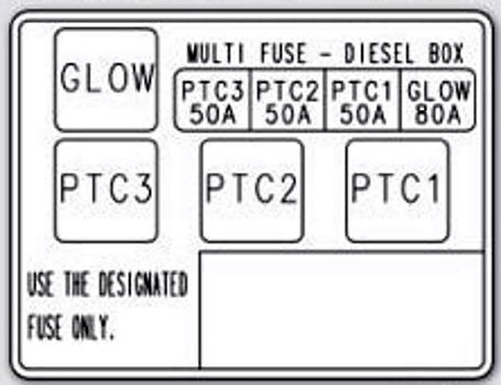
Installed on Kia Soul models with a diesel engine. The modules responsible for the operation of the auxiliary heating and glow plugs are located here.
In the passenger compartment
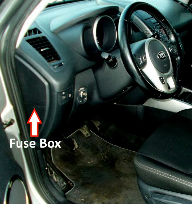
Located at the end of the dashboard behind the plastic trim.
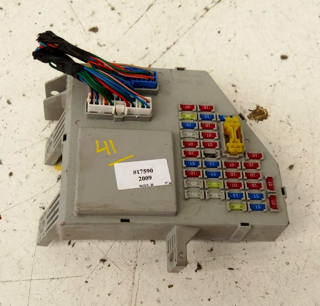
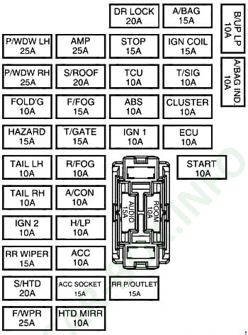
General view of the KIA Soul 1 interior fuse box.
| Diagram | ||
|---|---|---|
|
||
| Name | Amp / Legend | A |
| P / WDW LH | Main switch for power windows, switch for rear left door power window | 25 |
| P / WDW RH | Main switch for power windows, switch for rear right door power window, switch for power window of passenger's door | 25 |
| PDM 2 | Start / stop switch, PDM, key fob holder | 10 |
| FOLD'G | Data connector, external mirror power switch | 10 |
| HAZARD | Hazard Relay, One Touch Direction Indicator Interrupt, Hazard Switch | 15 |
| TAIL LH | License plate lamps, rear left combination lamp, left front headlight | 10 |
| TAIL RH | Rear right combination lamp, right headlight, illumination | 10 |
| IG 2 | BCM, headlight range control switch, left / right headlight range control actuator, roof sunroof control unit | 10 |
| RR WIPER | Instrument panel junction box (rear wiper relay), multi-function switch, rear wiper motor | 15 |
| F / WPR | Front wiper motor, multifunction switch, fuse box and M/O relay (relay 10) | 25 |
| AMP |
|
25 |
| S / ROOF | Sunroof control unit | 20 |
| F / FOG | Front fog lamp relay | 15 |
| T / GATE | Trunk lid relay, diagnostic socket | 15 |
| R / FOG | Rear fog lamp relay | 10 |
| A / CON | Air conditioner control unit, engine compartment relay and fuse box (relay 1, relay 5, relay 6), DSL relay and fuse box (PTC 2 relay, PTC 3 relay) | 10 |
| H / LP | PDM (Low Beam Relay) | 10 |
| ACC | PDM, audio system, amplifier, ISG low-voltage DC system (audio/amplifier), decorative lighting module, BCM, electronic key control unit, electric rearview mirror switch | 10 |
| ACC SOCKET | Front power outlet, KIA Soul cigarette lighter fuse | 15 |
| HTD MIRR | ECM / PCM, Driver / Passenger Side Power Mirror Motor, A / C Control Module | - |
| DR LOCK | Door lock relay, door unlock relay, double lock relay | - |
| STOP | Brake light switch, brake light relay, engine compartment relay and fuse box (relay 8, multifunction diagnostic connector) | 15 |
| TCU | Vehicle speed sensor (manual transmission), transmission range switch (automatic transmission), ATM lever indicator | 10 |
| ABS | ESP switch, steering angle sensor, ABS / ESP control unit, multi-functional diagnostic socket | 10 |
| IG 1 | Engine compartment relay and fuse box (relay 8, relay 9), brake light switch, oil pump inverter, parking assist unit, front left/right seat heater, low voltage DC-DC ISG (audio/amplifier), front left/right seat heater switch, seat belt reminder unit, electrochromic mirror, SBR indicator, reverse parking assist buzzer, ISG switch, tire pressure monitor | 10 |
| RR P / OUTLET | Rear power outlet, cigarette lighter | 15 |
| A / BAG | SRS control unit, passenger airbag indicator | 15 |
| IGN COIL | G4FC / G4FD: Ignition coil # 1 ~ 4, capacitor | 15 |
| T / SIG | Hazard Switch, Multi Function Switch | 10 |
| CLUSTER | BCM, air conditioning control unit, PDM, electronic key control unit, instrument cluster | 10 |
| ECU | ECM / PCM, air flow sensor, under-hood fuse / relay box (relay 2), fuel filter warning sensor | 10 |
| START | PDM, Transmission Range Switch, Ignition Lock Switch, ECM / PCM | 10 |
| B / UP LP | Reversing light switch | 10 |
| A / BAG IND | Instrument cluster (indicators) | 10 |
| AUDIO | HF receiver, with ISG: Low-voltage DC / DC converter ISG (audio system), without ISG: Audio system | 15 |
| ROOM | BCM, ignition switch and door switch, instrument cluster, tire pressure monitor module, air conditioning control unit, sun visor lamp, center light, directional light, outside mirror switch, trunk light | 10 |
Behind the fuse block, under the panel, there is a separately mounted relay block of the power distribution module, which is responsible for the start/stop button and its illumination.
