
The first-generation Lexus GS 300 corresponds to the Japanese-market Toyota Aristo (JZS147 platform), which debuted in 1991 on the Crown Majesta architecture. Designed by Giorgetto Giugiaro’s renowned Italdesign studio, the Aristo featured a striking, sophisticated profile suitable for a premium mid-size luxury sedan. This guide provides comprehensive fuse and relay box diagrams, terminal assignments, and component locations for the 1st-generation Toyota Aristo (S140/JZS147 series) and Lexus GS 300 (S140 series) produced from 1991 through 1997.
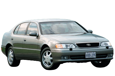
Below are the locations, photographic views, and schematics for the electrical power distribution centers. The fuse protecting the “Cigarette Lighter” circuit is highlighted in bold.
Engine Compartment Power Distribution Center
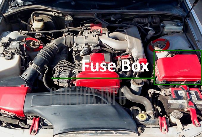
Located adjacent to the 12V battery, protected by a sealed plastic cover.

Typical engine compartment fuse box layout.
| Engine Compartment Fuse Box Diagram | ||
|---|---|---|
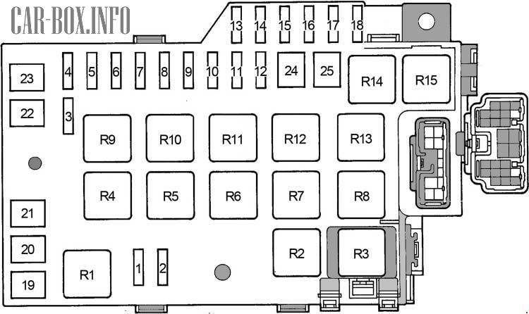
|
||
| No. | Circuit Protected | Rating (A) |
| 1 | Fog Lamps (FOG) | 15 |
| 2 | Daytime Running Lights (DRL) | 7.5 |
| 3 | Traction Control System (TRAC) | 10 |
| 4 | Interior Dome Light, Power Sunroof, Cruise Control, Door Ajar Indicator, Map Light, Luggage Compartment Lamp, Courtesy Lamps, Footwell Illumination, Ignition Switch Light, ABS Clock, Power Antenna, Audio System, Anti-Theft System, Wireless Keyless Entry (DOME) | 10 |
| 5 | Wireless Remote Control ECU, ABS ECU, TRC ECU, Cruise Control ECU, DRL Controller, A/C Control Unit (ECU-B) | 7.5 |
| 6 | Charging System Voltage Sensing (ALT SENSING) | 7.5 |
| 7 | Multiport Fuel Injection System (SFI/MFI), SRS Airbag System, Battery Charge Warning Lamp, Ignition System, Instrument Cluster, Service Indicators, Warning Buzzer (AM2) | 15 |
| 8 | Cellular Telephone (TEL) | 15 |
| 9 | Hazard Warning Flasher, Dual Horns (HAZ. HORN) | 20 |
| 10 | Transmission Control Module (TCM), Multiport Fuel Injection System (EFI/ECU), Toyota Aristo / Lexus GS 300 Fuel Pump Circuit (EFI) | 20 |
| 11 | Audio System, Power Antenna (RADIO1) | 25 |
| 12 | Ignition System Primary Circuit (IG2) | 30 |
| 13 | 1996–1997 MY: Data Link Connector / Diagnostic Port (OBD II) | 7.5 |
| 14 | Right Headlamp Circuit (HEAD RH) | 15 |
| Right High-Beam Headlamp (HEAD RH-UPR) | 10 | |
| 15 | Left Headlamp Circuit (HEAD LH) | 15 |
| Left High-Beam Headlamp (HEAD LH-UPR) | 10 | |
| 16 | Right Low-Beam Headlamp (HEAD RH-LWR) | 10 |
| 17 | Left Low-Beam Headlamp (HEAD LH-LWR) | 10 |
| 18 | Radiator Cooling Fan Motor (RDI FAN) | 30 |
| 19 | Unused / Vacant | |
| 20 | Ignition Switch Power, Fuses: “ECU-IG”, “WIPER”, “GAUGE”, “TURN”, “SEAT-HTR”, “CIG” (AM1) | 40 |
| 21 | Blower Motor / Heater Relay (HEATER) | 50 |
| 22 | Cooling Fan Main Relay, Traction Control Relay, Anti-lock Brake System Actuator Relay, Fuses: “TRAC” (ABS) | 60 |
| 23 | Tail Lamp Relay, Alternator / Generator, Fuses: “FOG”, “AM1”, “HEATER”, “DEFOG”, “ABS”, “STOP”, “SRS”, “POWER” (ALT) | 100 |
| 24 | Headlamp Main Relay, DRL Relay No. 2, Starter Relay (MAIN) | 50 |
| 25 | Traction Control Pump Motor, ABS Hydraulic Pump Motor (ABS2) | 40 |
| Relay Terminal Assignments | ||
| R1 | Daytime Running Light Relay No. 3 | |
| R2 | Radiator Cooling Fan Relay | |
| R3 | Daytime Running Light Relay No. 2 | |
| R4 | Heater Blower Motor Relay | |
| R5 | Short Pin / Jumper Plug | |
| R6 | A/C Compressor Magnetic Clutch Relay | |
| R7 | Starter Motor Relay | |
| R8 | ABS Pump Motor Relay | |
| R9 | ABS Control Relay | |
| R10 | Radiator Cooling Fan Main Relay | |
| R11 | Ignition Power Relay (IG2) | |
| R12 | Headlamp Main Relay | |
| R13 | Traction Control (TRAC) System Relay | |
| R14 | Horn Relay | |
| R15 | Engine Control Module Main Relay (EFI) | |
| Underhood Electronic Module Locations | |
|---|---|

|
|
| 1 | Underhood Fuse/Relay Box |
| 2 | Headlamp Washer Relay Unit |
| 3 | Traction Control (TRAC) Relay Unit |
Passenger Compartment Fuse Block
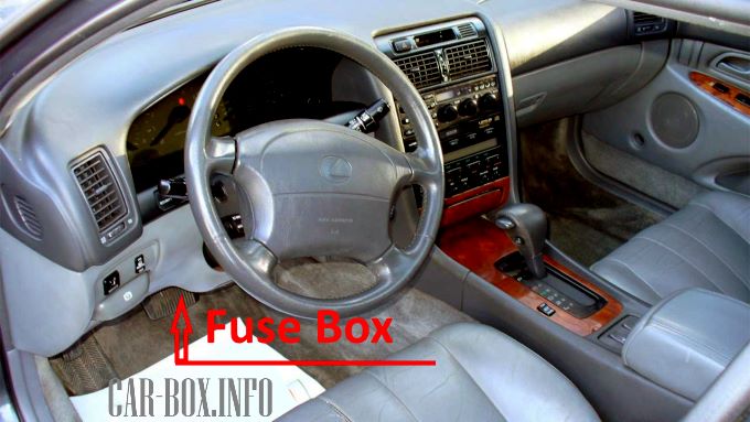
The junction block is positioned beneath the driver’s side dashboard (Left-Hand Drive models) or under the glove box assembly on the passenger side (Right-Hand Drive models). The interior relay box is mounted directly adjacent to it on the kick panel.
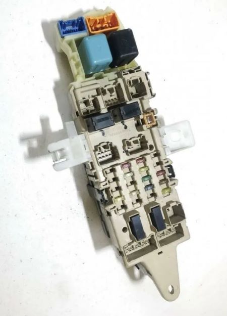
Junction Block Overview (Configuration 1).
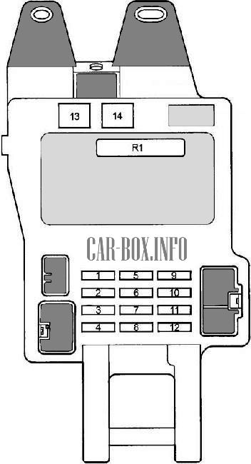
| Passenger Compartment Fuse Assignments (Configuration 1) | ||
|---|---|---|
|
||
| No. | Circuit Protected | Rating (A) |
| 1 | Heated Seats | 15 |
| 2 | Stop Lamps, High-Mount Stop Lamp, Shift Interlock System, ABS ECU, TRC ECU, Electronic Fuel Injection (EFI/SFI) ECU | 20 |
| 3 | Instrument Cluster Gauge Assembly, Backup/Reverse Lamps, Rear Window Defogger Timer, Heated Power Mirrors, Climate Control Unit, A/C ECU, Service Indicators, Warning Buzzer, Alternator/Charging System, Shift Indicator Lamps, DRL Controller | 15 |
| 4 | Shift Interlock Solenoid, Cellular Phone, Power Door Locks, Seat Belt Control Module, ABS ECU, TRC ECU, Power Steering ECU, Cruise Control ECU, Power Tilt/Telescopic Steering Column, Power Antenna, Radiator Fan ECU, Combination Switch Illumination, Automatic Lighting Control Unit, Shift Lever Illumination | 10 |
| 5 | Cigarette Lighter Power Outlets (Lexus GS 300 / Toyota Aristo JZS147) (Front / Rear), Digital Clock, Climate Control Module, Audio System Head Unit, Shift Interlock Module, SRS Airbag ECU, Power Door Lock Relay, Power Exterior Mirrors, Power Antenna, Anti-Theft Alarm System | 15 |
| 6 | Unused / Vacant | - |
| 7 | Turn Signal Flasher Circuit | 10 |
| 8 | 1991–1993 MY: Windshield Wiper/Washer Motor, Headlamp Washers | 15 |
| 1994–1997 MY: Windshield Wiper/Washer Motor, Headlamp Washers | 20 | |
| 9 | Shift Indicator Illumination, Climate Control Panel, Hazard Switch Illumination, Glove Box Lamp, Ashtray Lamp, Clock Illumination, Cigarette Lighter Illumination, Audio System Illumination, Gear Selector Lever Illumination, Instrument Cluster Backlighting, DRL System | 7.5 |
| 10 | Supplemental Restraint System (SRS Airbag ECU) | 7.5 |
| 11 | Tail Lamps, Parking Lamps, License Plate Lamps | 10 |
| 12 | Heated Exterior Mirrors | 10 |
| 13 | Power Windows, Power Sunroof, Power Seats, Central Locking System, Power Steering Column Adjustment, Main Power Circuit Relay (POWER) | 30 |
| 14 | Rear Window Defogger Switch, Fuse: “MIR HTR” | 40 |
| R1 | Integrated Relay Module | |
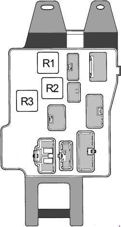
| Relay Locations (Rear Side of Junction Block) | ||
|
||
| R1 | Short Pin / Jumper Connector | |
| R2 | Parking / Tail Lamp Relay | |
| R3 | Rear Window Defogger Relay | |
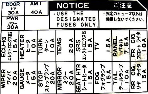
| Passenger Compartment Fuse Block (Configuration 2) | |
|---|---|
|
|
| Designation | Circuit Protected |
| TURN | Turn Signal Indicators and Flasher Relay |
| WIPER | Windshield Wiper and Washer System, Headlamp Cleaners |
| PANEL | Shift Selector Illumination, HVAC Control Panel, Hazard Switch Illumination, Glove Box Light, Ashtray Light, Digital Clock, Cigarette Lighter Illumination, Audio Backlighting, Instrument Cluster Illumination, DRL Indicator |
| SRS | SRS Airbag System Control Module |
| TAIL | Parking/Side Marker Lamps, License Plate Illumination |
| MIR HTR | Heated Exterior Mirrors |
| SEAT HTR | Heated Front Seats |
| STOP | Stop Lamps, High-Mount Brake Lamp, Shift Interlock Solenoid, ABS ECU, TRC ECU, Engine Control Module (EFI/SFI) |
| GAUGE | Instrument Cluster Gauges, Reversing/Backup Lamps, Rear Defogger Relay, Heated Mirror Relay, HVAC Control Unit, A/C Amplifier, Maintenance Warning Lights, Warning Buzzer, Charging System, Shift Position Display, DRL Module |
| ECU-IG | Shift Interlock System, Cellular Phone, Power Door Locks, Seat Belt Control Unit, ABS ECU, TRC ECU, Progressive Power Steering ECU, Cruise Control Module, Power Tilt/Telescopic Steering, Power Antenna Relay, Cooling Fan Control ECU, Instrument Backlighting Control, Automatic Headlamp Control Module |
| CIG | Cigarette Lighter Outlet (Toyota Aristo JZS147 / JZS141) (Front / Rear), Digital Clock, HVAC Module, Audio Unit, Shift Interlock System, SRS Airbag Control Module, Power Locks, Power Mirror Controls, Power Antenna, Anti-Theft Control Module |
| POWER | Power Windows, Power Sunroof, Power Seats, Central Locking System, Power Steering Column Adjuster, Main Power Relay (POWER) |
| DEFOG | Rear Window Defogger Circuit, Fuse: “MIR HTR” |
| DOOR | Door Courtesy Switch Circuits, Central Door Locking Module |
| Cabin Relay Box | |
|---|---|

|
|
| No. | Component Designation |
| R1 | Turn Signal & Hazard Flasher Relay |
| R2 | Daytime Running Light Relay No. 4 |
| R3 | Front Fog Lamp Relay |
| R4 | Main Power Relay (Power Windows, Sunroof, Central Locking, Steering Column, Power Seats) |
| Passenger Compartment Electronic Module Locations | |
|---|---|

|
|
| 1 | Integrated Relay Module |
| 2 | Daytime Running Light (DRL) Control Relay |
| 3 | Cabin Relay Box |
| 4 | Anti-Theft Alarm Control ECU |
| 5 | Passenger Compartment Fuse Box |
| 6 | Windshield Wiper Relay |
| 7 | Power Junction/Distribution Block |
| 8 | Air Conditioning (A/C) Control ECU |
| 9 | Traction Control (TRAC) ECU |
| 10 | A/C Amplifier Assembly |
| 11 | ABS and Traction Control (ABS/TRC) Integrated ECU |
| 12 | Heater Blower Motor Relay |
| 13 | Engine Control Module (ECM – Manual Transmission) / Engine and Transmission Control Module (PCM – Automatic Transmission) |
| 14 | Shift Interlock Control ECU |
| 15 | SRS Airbag Center Sensor Assembly |
| 16 | Cruise Control ECU |
| 17 | Progressive Power Steering (PPS) ECU |
| 18 | Power Tilt and Telescopic Steering Column ECU |
Chassis & Body Electrical Components
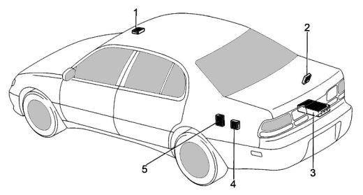
Component Locations: 1. Power Sunroof Relay, 2. Door Lock Control ECU, 3. Audio System Power Amplifier, 4. Power Antenna Relay, 5. Fuel Pump Control ECU
