
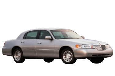
In this article, we take a detailed look at the fuse and relay box diagrams for the Lincoln Town Car (third generation, FN145: 1997, 1998, 1999, 2000, 2001, and 2002 model years).
Fuses #23 in the passenger compartment panel and #24 in the engine compartment panel power the cigarette lighter and auxiliary power outlets.
Engine Compartment
The engine compartment houses the main fuse box and an auxiliary relay box.
Main Fuse Box
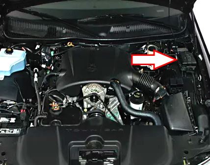
Located on the left side of the engine bay, under the protective cover.
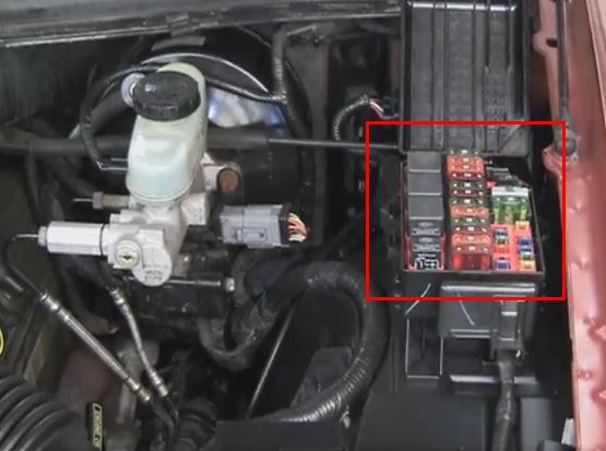
Fuse box location.
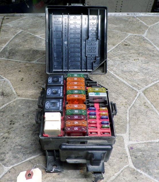
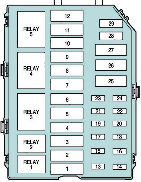
General view of the fuse box.
| Diagram | ||
|---|---|---|
|
||
| No. | Description | Rating |
| R1 | Fuel Pump Relay | |
| R2 | A/C Clutch Relay | |
| R3 | PCM Power Relay | |
| R4 | Air Suspension Relay | |
| R5 | Rear Window Defroster Relay | |
| 1 | Ignition Switch | 50 A |
| 2 | 40 A | |
| 3 | Cooling Fan (High Speed) | 50 A |
| 4 | PCM Power Relay | 30 A |
| 5 | Fuses #11, #19, #21, #23, #25, #27, and #32 in the passenger compartment panel | 40 A |
| 6 | 1997–2000: Starter Relay / Starter Motor | 30 A |
| 7 | 2001–2002: Fuses #1, #3, #5, #7, #9, and #31 in the passenger compartment panel | 40 A |
| 1997–2000: Fuses #1, #3, #5, #7, #9, and #31 in the passenger compartment panel | 50 A | |
| 8 |
|
30 A |
| 9 | 2001–2002: Anti-lock Brake System (ABS) Module | 40 A |
| 1997–2000: Anti-lock Brake System (ABS) Module | 50 A | |
| 10 | 2000–2002: Fuse #28 in the passenger compartment panel / All years: Rear Window Defroster | 40 A |
| 11 | Signature & Cartier: Accessory Delay Relay / Executive: Power Window Relay / Fuse #29 in the passenger compartment panel | 40 A |
| 12 | Air Suspension Module | 30 A |
| 13 | 2001–2002 (Long Wheelbase only): Rear Heated Seats | 30 A |
| 1997–2000: Charging System | 15 A | |
| 14 | 2001–2002 (Long Wheelbase only): Rear Auxiliary Power Outlet | 20 A |
| 1997–2000: Fuel Pump | 20 A | |
| 15 | 2001–2002 (Long Wheelbase only): Rear Auxiliary Power Outlet | 20 A |
| 1998: Airbag Supplemental Restraint System (SRS) | 10 A | |
| 16 | Heated Seats | 30 A |
| 17 | Air Suspension Module | 10 A |
| 18 | Horn Relay | 15 A |
| 19 | Fuse #33 in the passenger compartment panel, Audio Subwoofer | 30 A |
| 20 | 2001–2002: PCM / All years: Fuel Injectors | 15 A |
| 21 | Transmission Solenoids, Heated Oxygen Sensors (HO2S), EGR Vacuum Regulator, EVAP Canister Vent Solenoid, EVAP Vapor Management Valve | 15 A |
| 22 | 2001–2002: Fuel Pump | 20 A |
| 23 | 2001–2002: Charging System | 15 A |
| 24 | Auxiliary Power Outlet / Cigarette Lighter | 20 A |
| 25 | Front Passenger Power Seat, Power Lumbar Support | 30 A |
| 26 | Circuit Breaker: Cooling Fan (Low Speed) | 30 A |
| 27 | 2001–2002: Anti-lock Brake System (ABS) Module | 20 A |
| 28 | PCM Diode | — |
| 29 | Not used | — |
Auxiliary Relay Block
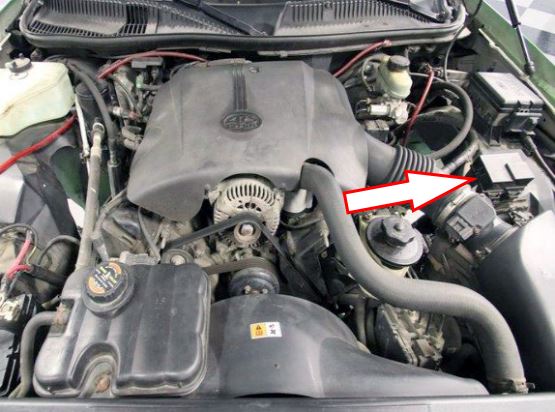
Located near the air cleaner assembly.
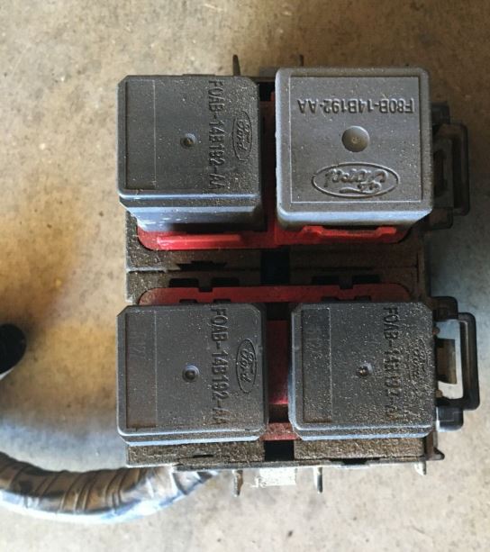
Relay block location.
| Diagram | |
|---|---|

|
|
| No. | Description |
| R1 | Cooling Fan Relay (Low Speed) |
| R2 | Cooling Fan Relay (High Speed) |
| R3 | Starter Relay |
| R4 | Horn Relay |
Passenger Compartment
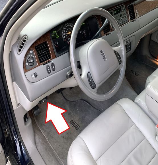
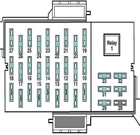
Located under the driver-side instrument panel, to the left of the brake pedal.
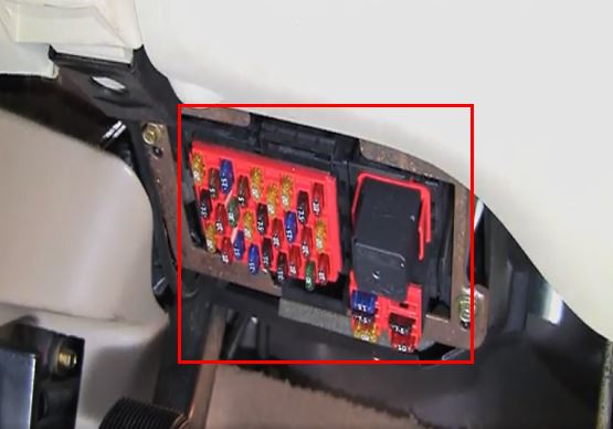
Accessing the interior fuse panel.
| Diagram | ||
|---|---|---|
|
||
| No. | Description | Rating |
| R1 |
|
|
| 1 | Left Headlamp Low Beam, Lighting Control Module (LCM) | 10 A |
| 2 | Blower Motor (EATC) | 30 A |
| 3 | Right Headlamp Low Beam, Lighting Control Module (LCM) | 10 A |
| 4 | Instrument Cluster | 7.5 A |
| 5 |
|
7.5 A |
| 6 | Heated Seats, Electronic Automatic Temperature Control (EATC) | 15 A |
| 7 | 2001–2002: Park/Tail Lamps / All years: Lighting Control Module (LCM), Auto-Dimming Day/Night Sensor, Audio Amplifier | 15 A |
| 8 | Speed Control (Cruise Control), Shift Interlock, Steering Wheel Rotation Sensor, Air Suspension Module | 10 A |
| 9 | Headlamp High Beams, Multifunction Switch, Lighting Control Module (LCM) | 20 A |
| 10 | 2001–2002: Airbag System, Restraint Control Module (RCM) | 10 A |
| 1997–2000: Stop Lamps, Brake Pedal Position (BPP) Switch, Brake Pressure Switch | 20 A | |
| 11 | 1997–2000: Airbag Electronic Crash Sensor | 10 A |
| 12 | Passive Anti-Theft System (PATS), Instrument Cluster, Ignition Coils, Ignition Switch | 15 A |
| 13 | Traction Control Switch, Anti-lock Brake System (ABS) Module | 10 A |
| 14 | 2001–2002: Vehicle Communication System (VCS) / All years: Lighting Control Module (LCM), Transmission Control Switch (O/D Off) | 7.5 A |
| 15 | Turn Signals, Multifunction Switch | 20 A |
| 16 | Windshield Wiper Motor, Wiper Control Module | 30 A |
| 17 | Electrochromic (EC) Auto-Dimming Mirrors, Backup Lamps, Digital Transmission Range (DTR) Sensor | 10 A |
| 18 |
|
7.5 A |
| 19 | Powertrain Control Module (PCM), EATC Module, Instrument Cluster, Digital Clock | 10 A |
| 20 | Shift Interlock, Digital Clock, Lighting Control Module (LCM) | 7.5 A |
| 21 | Hazard Lamps, Multifunction Switch | 20 A |
| 22 |
|
20 A |
| 23 |
|
20 A |
| 24 | Front Audio Module / Head Unit | 5 A |
| 25 | Courtesy and Interior Demand Lamps, Lighting Control Module (LCM) | 15 A |
| 26 | Starter Relay Coil, Digital Transmission Range (DTR) Sensor | 5 A |
| 27 | Fuel Filler Door Release Switch | 20 A |
| 28 | Heated Exterior Mirrors | 10 A |
| 29 | Driver Door Module (DDM), Trunk Lid Release, Power Door Locks | 20 A |
| 30 | Driver Seat Module, Driver Door Module (DDM), Power Door Lock Switches, Trunk Lid Release Switch, Driver Seat Control Switch, Power Mirror Switch | 7.5 A |
| 31 | Lighting Control Module (LCM), Main Light Switch | 7.5 A |
| 32 | 2001–2002: Brake Pressure Switch, Brake Pedal Position (BPP) Switch, Fuses #20 and #22 | 25 A |
| 33 |
|
15 A |

this is great!! right to the Point..it is ROYAL!
How do the relay slash fuses come out it is like a tug of war do i need rope?