The third generation of Mazda 2 hatchback debuted at the Geneva and Shanghai Motor Show in 2007. The car is built on the DE platform, on it is built Ford Fiesta of the sixth generation. In this article, we will take a detailed look at the fuse box diagrams for the Mazda 2 (3rd generation; codename DE) 2007, 2008, 2009, 2010, 2011, 2012, 2013, 2014, 2015, 2016 years of manufacture.
Here you will find the locations and photos of distribution boxes. The fuses responsible for the “Cigarette lighter” and “Fuel Pump” are highlighted in bold.
In the engine compartment
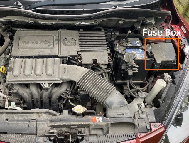
The distribution box is located near the battery. Remove the plastic cover to access it.
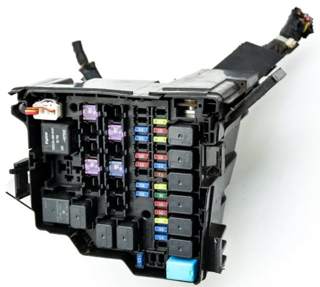
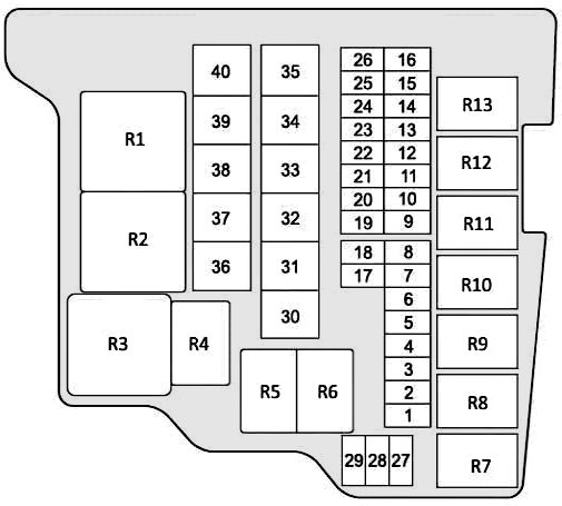
General view.
| Diagram | ||
|---|---|---|
|
||
| № | Relay assignment | |
| R1 | Not used | |
| R2 | Glow plug relay | |
| R3 | Engine control relay | |
| R4 | High beam relay | |
| R5 | Headlamp low beam relay | |
| R6 | Rear fog lamp relay | |
| R7 | Petrol: Fuel pump relay | |
| R8 | Heater blower motor relay | |
| R9 | Not used | |
| R10 | Horn relay | |
| R11 | Air conditioner relay | |
| R12 | Starter relay | |
| R13 | Fog lamp relay | |
| № | Fuse designation | Amps |
| 1 | Fuel heating | - |
| 2 | Fuel pump fuse | 15 |
| 3 | F.FOG - Fog lights | 15 |
| 4 | Power windows | 20 |
| 5 | Horn | 10 |
| 6 | EG1 - Engine management system | 10 |
| 7 | DSC-P - DSC | 30 |
| 8 | DSC-V - DSC | 20 |
| 9 | Conditioner | 7.5 |
| 10 | TAIL - tail lights, parking lights, license plate illumination lamp | 15 |
| 11 | STOP - Stop lamps | 10 |
| 12 | SWS - Safety Airbags | 7.5 |
| 13 | R.DEF - Heated rear window | 20 |
| 14 | HAZARD - Warning lamps, direction indicators | 10 |
| 15 | D / L - Electrical door locks | 20 |
| 16 | EOP | - |
| 17 | ENG BAR - Engine management system | 15 |
| 18 | ENG INJ - Engine management system | 15 |
| 19 | ENG INJ2 - Engine management system | - |
| 20 | H / L HI RH - High beam halogen lamps (right) | - |
| 21 | H / L HI LH - High beam halogen lamps (left) | - |
| 22 | DCDC3 - Optional Equipment | - |
| 23 | H / L LO RH - Dipped beam headlight (right) | 15 |
| 24 | H / L LO LH - Dipped beam headlight (left) | 15 |
| 25 | AUDIO2 - Audio system | - |
| 26 | DSC-V2 | - |
| 27 | HORN2 - Sound Signal 2 | - |
| 28 | METER - Instrument cluster | - |
| 29 | ROOM - Interior light | 15 |
| 30 | GLOW - Glow Plugs | - |
| 31 | EWT | - |
| 32 | IG KEY 1 - For protection of various circuits | 40 |
| 33 | FAN 3 - Cooling Fan | - |
| 34 | FAN 2 - Cooling Fan | 30 |
| 35 | FAN 1 - Cooling Fan | - |
| 36 | INJ - Engine Management | - |
| 37 | IG KEY 2 - For protection of various circuits | 30 |
| 38 | 4WD system | - |
| 39 | ABS DSC-P2 - ABS | - |
| 40 | BLOWER - Air conditioner fan | 30 |
In the passenger compartment
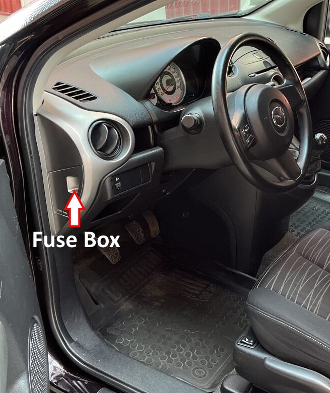
The distribution box is located in the driver's side end of the dashboard. Remove the end trim for access.
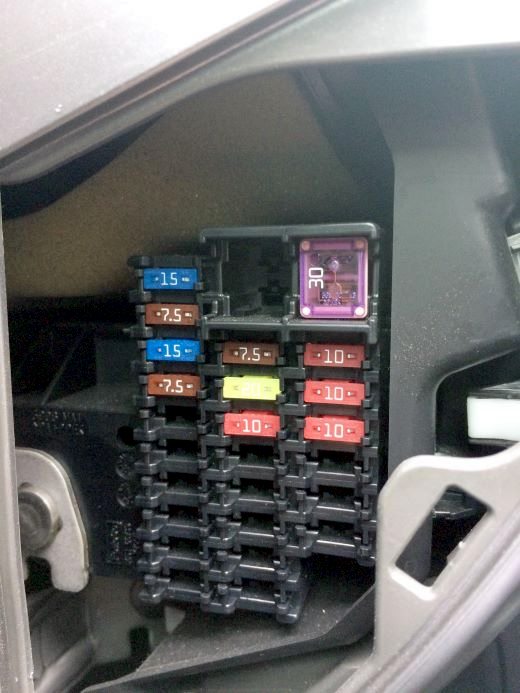
Access example.
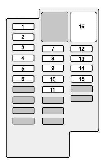
| Diagram | ||
|---|---|---|
|
||
| № | Description | Amps |
| 1 | TCM - Electronic transmission control unit | 10 |
| 2 | ILLUMI - Dashboard illumination | 7,5 |
| 3 | CIGAR - Mazda 2 Cigarette lighter fuse, auxilary power outlet | 15 |
| 4 | MIRROR - Power mirrors | 7,5 |
| 5 | M.DEF - Heated mirrors | 7,5 |
| 6 | S.WARM - Heated seats | - |
| 7 | A / C - Air Conditioning | 7,5 |
| 8 | F.WIP - Windshield wiper and windshield washer | 20 |
| 9 | R.WIP - Rear window wiper and washer | - |
| 10 | Starter | - |
| 11 | METER 2 - Dashboard | - |
| 12 | ENG - Engine management system | 10 |
| 13 | METER - Instrument cluster | 10 |
| 14 | SAS - Airbag, DSC | 10 |
| 15 | AUDIO 3 - Audio system | - |
| 16 | Power windows | 30 |
General location
Placement of electronic control units.

|
|
| № | Appointment |
| 1 | ABS electronic control unit |
| 2 | Heater fan motor resistor / A / C - under the dashboard |
| 3 | Air conditioner electronic control unit |
| 4 | Anti-theft control unit |
| 5 | Battery |
| 6 | Diagnostic connector (DLC) |
| 7 | Electronic engine control unit |
| 8 | Cooling fan motor resistor - next to the radiator |
| 9 | Fuse / relay box, engine compartment 1 |
| 10 | Fuse / relay box, engine compartment 2 |
| 11 | Fuse / relay box, engine compartment 3 - diesel |
| 12 | Fuse / relay box, instrument panel |
| 13 | Horn 1 |
| 14 | Horn 2 |
| 15 | Keyless entry system control unit |
| 16 | Multifunction control unit - functions: Fog lights, signal lights, headlights, turn indicators, seat belt monitoring system windshield wipers |
| 17 | Ambient temperature sensor - behind the front bumper |
| 18 | Power steering control unit |
| 19 | SRS electronic control unit |
| 20 | Electronic transmission control unit - in the engine control unit |
