The updated Mazda Demio, presented in 2002, was based on the DY platform. The name Demio remained on the Japanese market, but it was decided to abandon the index 121 used for other markets, it was replaced by a simpler - 2. In this article, we will take a detailed look at the fuse box diagrams for the Mazda 2 (second generation; codename DY) 2002, 2003, 2004, 2005, 2006, 2007 years of manufacture.

Here you will find the locations and photos of distribution boxes. The fuses responsible for the “Cigarette lighter” and “Fuel Pump” are highlighted in bold.
In the engine compartment
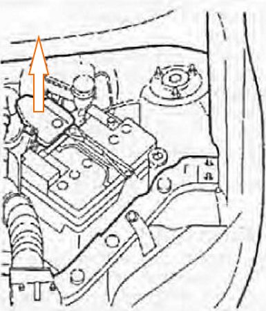
Located behind the protective cover near the battery.
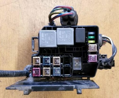
Generar view.
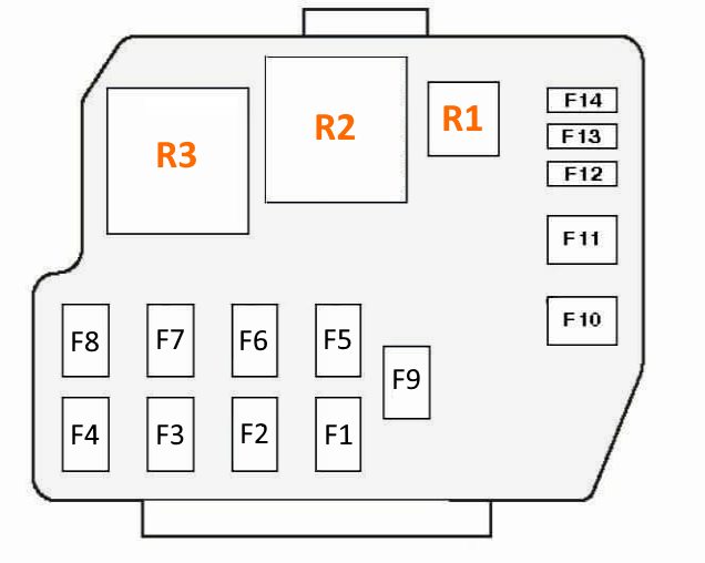
| Diagram | ||
|---|---|---|
|
||
| № | Description | Amps |
| R1 | Full Throttle Position Relay (Air Conditioning) | |
| R2 | Cooling fan motor relay (high speed) | |
| R3 | Cooling fan motor relay | |
| F1 | Glow plugs (Diesel), auxiliary heater | 50 |
| F2 | Air conditioner/heater fan motor | 40 |
| F3 | Ignition switch | 50 |
| F4 | Cooling fan motor | 50 |
| F5 | Automatic clutch control | 60 |
| F6 | Ignition switch | 60 |
| F7 | Headlights | 30 |
| F8 | Engine management | 60 |
| F9 | Battery Power Distribution | 100 |
| F10 | Heated rear window | 30 |
| F11 | Anti lock brake system (ABS) | 60 |
| F12 | Power windows | 20 |
| F13 | Central locking system | 30 |
| F14 | Fog lights | 15 |
In the passenger compartment
There are three distribution boxes here, which are responsible for protecting the vehicle's electrical circuits.
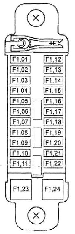
Primary fuse box
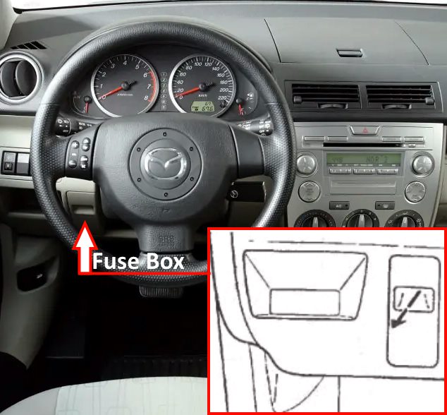
Located at the bottom of the dashboard. Remove the protective cover to access it.
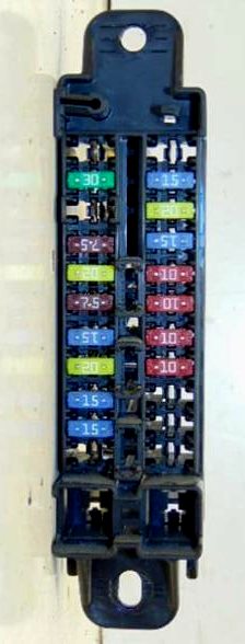
General view of the Mazda2 dy primary interior fuse box.
| Diagram | ||
|---|---|---|
|
||
| No. | Amps | Decoding |
| F1.01 | - | Not used |
| F1.02 | - | |
| F1.03 | 15 | Interior lighting |
| F1.04 | 15 | Mazda 2 cigarette lighter fuse |
| F1.05 | 7.5 | Power side mirrors |
| F1.06 | - | Not used |
| F1.07 | 10 | Instrument cluster |
| F1.08 | 20 | Windshield wipers and washers |
| F1.09 | 10 | Active safety system |
| F1.10 | 15 | engine management system |
| F1.11 | 15 | the engine control unit |
| F1.12 | 30 | Power windows |
| F1.13 | - | Not used |
| F1.14 | - | |
| F1.15 | - | |
| F1.16 | 7.5 | Starter |
| F1.17 | 7.5 | Back-up lights |
| F1.18 | 7.5 | Dashboard illumination |
| F1.19 | 7.5 | Air conditioner compressor solenoid clutch |
| F1.20 | 7.5 | Air conditioner |
| F1.21 | 10 | Rear door window wiper and washer |
| F1.22 | 10 | Tailgate window defroster |
| F1.23 | - | Not used |
| F1.24 | - | |
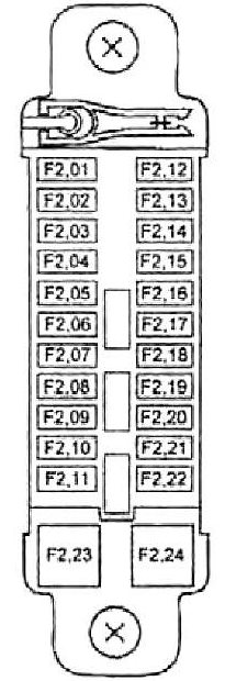
Auxiliary fuse box
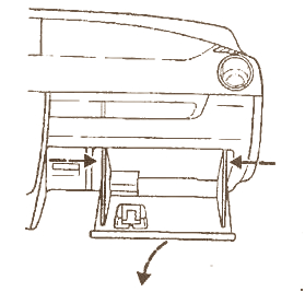
The auxiliary unit in the passenger compartment is behind the glove compartment.
| Diagram | ||
|---|---|---|
|
||
| No. | Amps | Description |
| F2.01 | - | Not used |
| F2.02 | 30 | ABS (abs system) |
| F2.03 | - | Not used |
| F2.04 | 7.5 | Alternator |
| F2.05 | 20 | fuel pump fuse |
| F2.06 | 7.5 | Electronic engine and transmission control unit |
| F2.07 | 15 | Air flow sensor, engine management system |
| F2.08 | 20 | |
| F2.09 | 15 | Brake lights |
| F2.10 | 15 | Alarm |
| F2.11 | - | Not used |
| F2.12 | - | |
| F2.13 | - | |
| F2.14 | 15 | TNS |
| F2.15 | 20 | ABS system |
| F2.16 | 15 | Heated side mirrors |
| F2.17 | 10 | High beam (right headlamp) |
| F2.18 | 10 | High beam (left headlamp) |
| F2.19 | 10 | Dipped beam (right headlamp) |
| F2.20 | 10 | Dipped beam (left headlamp) |
| F2.21 | - | Not used |
| F2.22 | - | |
| F2.23 | - | |
| F2.24 | - | |
Relay box
Located next to the auxiliary cabin unit.

Diagram.
| № | Decoding |
| 1 | Dipped beam relay |
| 2 | High beam relay |
| 3 | Fuel pump relay |
| 4 | Anti-theft alarm relay |
| 5 | Engine control relay |
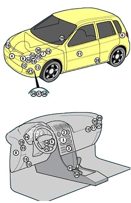
General location
Placement of electronic control units.
|
|
| № | Description |
| 1 | Air conditioner control unit (in the heater control panel) |
| 2 | Air conditioner/heater blower motor relay - behind the dashboard |
| 3 | Heater blower motor resistor / A / C - passenger footwell |
| 4 | Impact sensor (SRS), front |
| 5 | Anti-theft device control unit - behind the dashboard |
| 6 | Antitheft alarm sound |
| 7 | Battery |
| 8 | Central locking control box |
| 9 | Clutch actuator control unit - engine compartment |
| 10 | Diagnostic connector (DLC) |
| 11 | Power window control unit (in the switch on the driver's door) |
| 12 | Cooling fan motor resistor - radiator shell |
| 13 | Fog lamp relay |
| 14 | Fuse / relay box, engine compartment |
| 15 | Fuse / relay box, passenger compartment 1 |
| 16 | Fuse / relay box, passenger compartment 2 |
| 17 | Fuse / relay box, passenger compartment 3 |
| 18 | Headlamp range control motor, left-hand side |
| 19 | Headlamp range control motor, right-hand side |
| 20 | Rear window heater relay |
| 21 | Horn |
| 22 | Immobilizer ring antenna - next to the ignition switch |
| 23 | Turn signal breaker relay |
| 24 | Instrument cluster control unit (in the instrument panel) |
| 25 | Rear fog lamp relay |
| 26 | Rear window washer pump - integrated in windshield washer pump |
| 27 | Relay box - includes: Windshield wiper motor relay, windshield washer pump relay, rear window washer relay, horn relay, front/rear light relay |
| 28 | Side impact sensor, front left - lower part of the B-pillar |
| 29 | Side impact sensor, front right-bottom B-pillar |
| 30 | Starter relay |
| 31 | SRS electronic control unit |
| 32 | Electronic transmission control unit - in the electronic clutch control unit |
| 33 | Transmission shift actuator - to the gearbox |
| 34 | Shift control unit - automatic transmission selector lever |
| 35 | Vehicle speed sensor, with ABS system - ABS electronic control unit |
| 36 | Vehicle speed sensor, without ABS - at the checkpoint |
| 37 | Windshield washer fluid low level sensor |
| 38 | Windshield washer pump motor |
| 39 | Intermittent windshield wiper relay - switch assembly |
