The Actros was first introduced in 1996, production continued until 2003 and had innovative features such as electronically controlled air brake system, intelligent disc brakes. The most popular was the model with the index 1840. In this article, we will take a detailed look at the fuse box diagrams for the Mercedes Actros (1st Gen; MP1) - 1996, 1997, 1998, 1999, 2000, 2001, 2002, 2003 years of manufacture.
Here you will find the locations and photos of distribution boxes. The fuse responsible for the “cigarette lighter” is highlighted in bold.
In the cabin
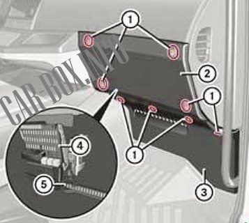
Located on the passenger side at the bottom of the dashboard. The protective cover must be removed for access.
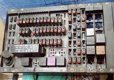
General view of the Mercedes Actros MP1 interior fuse box.
| Diagram | ||
|---|---|---|

|
||
| No. | Amps | Description |
| F1 | 10 | Rear fog lights, including on the trailer |
| F2 | 10 | Instrument cluster lighting / switch illumination, headlamp wiper, headlamp angle adjustment system, Mounting block - terminal 58 |
| F3 | 10 | Additional direction indicators |
| F4 | 10 | Liftable top hatch, 24 V radio, handbrake - terminal 30 |
| F5 | 10 | Working headlight, LSVA (heavy goods transport charges depending on the vehicle's payload) - terminal 30 |
| F6 | 10 | Spare |
| F7 | 15 | Mounting block - terminal D+ |
| F8 | 10 | Mirror heating system |
| F9 | 15 | 24 V power outlets |
| F10 | 10 | Digital tachograph, instrument cluster, diagnostic connector - terminal 30 |
| F11 | 20 | Trailer socket - terminal 30 |
| F12 | 20 | Trailer ABS Power Socket - Terminal 30 |
| F13 | 10 | Interior lighting, Toll Collect system - terminal 30 |
| F14 | 10 | headlamp cleaner |
| F15 | 10 | Three-phase alternator, gearbox, LSVA (heavy goods transportation charges based on vehicle payload) - terminal 15 |
| F16 | 10 | Power take-off devices |
| F17 | 20 | Heater fan, air conditioner |
| F18 | 5 | Instrument Cluster, Radio, Telephone, Speakerphone, Fax - Terminal 15R |
| F19 | 10 | Mercedes actros cigarette lighter fuse |
| F20 | 15 | Switch box on passenger side |
| F21 | 15 | Switch box on the driver's door |
| F22 | 10 | Windshield Washer, Hazard Warning - Clamp 30 |
| F23 | 10 | Dipped beam right |
| F24 | 10 | Dipped beam left |
| F25 | 10 | High beam right |
| F26 | 10 | High beam left, high beam indicator |
| F27 | 10 | Rear position lamp, parking light, side position lamps on the left, trailer power socket, Toll Collect system |
| F28 | 10 | Rear position lamp, parking light, side position lamps on the right side, trailer power socket |
| F29 | 15 | Transmission control system |
| F30 | 10 | Motor operation control - terminal 15, dangerous goods vehicles (GGVSE): emergency switch NOT-AUS |
| F31 | 10 | Driver's door switch unit, exterior mirror position setting, exhaust aftertreatment system unit - terminal 15 |
| F32 | 10 | All-wheel drive, ESP® system, additional water heating system |
| F33 | 10 | Windscreen washer, alarm, trailer socket - terminal 15 |
| F34 | 10 | Brake signal light, reversing light, trailer power socket |
| F35 | 10 | Condensate sensor, trailer ABS system power supply socket - terminal 15 |
| F36 | 15 | Additional water heating system |
| F37 | 10 | windshield washer |
| F38 | 10 | Digital tachograph, instrument cluster, safety airbag - terminal 15 |
| F39 | 10 | Horn (beep), Toll Collect, Diagnostic Connector, FleetBoard® System, Distributor - terminal 15 |
| F40 | 10 | Differential lock mechanism |
| F41 | 10 | Seat heating system |
| K3 | ABS/BS/EPB system | |
| K4 | Starter/battery relay | |
| K5 | D+ | |
| K6 | Stop lamps | |
| K7 | Back-up lamps | |
| Diagram of additional sections | ||
|---|---|---|

|
||
| No. | Amps | Description |
| A1 | 10 | Auxiliary heating system clock, FleetBoard® system, Toll Collect system - terminal 30 |
| A2 | 20 | Additional heating system |
| A3 | 15 | Central locking system |
| A4 | 15 | Comfortable locking system |
| A5 | 10 | Electronic braking system, portable lamp power socket - terminal 15 |
| A6 | 15 | 12 V power socket |
| A7 | 10 | Voltage transformer for 24V / 12V |
| A8 | 10 | Central locking system / comfort control locking system, radio remote control, retarder |
| A9 | 10 | Compressed air dryer |
| A10 | 15 | Distributor - terminal 30 |
| A11 | 15 | Exhaust gas aftertreatment unit - terminal 30 |
| A12 | 10 | Tail lift |
| A13 | 10 | Gearbox control system |
| A14 | 10 | Work lamp, retarder |
| B1 | 20 | Windshield heating system |
| B2 | 10 | Daytime Running Lights |
| B3 | 10 | Windshield heating system |
| B4 | 10 | Transmission oil cooler, cold box / 25A Allison transmission oil cooler |
| B5 | 15 | Electronic-hydraulic independent power steering |
| B6 | 10 | |
| B7 | 10 | Additional headlight |
| B8 | 10 | Flashing Light |
| B9 | 15 | Electronic brake system - terminal 30 |
| B10 | 10 | Telephone / navigation system control panel, cell phone - terminal 30 |
| B11 | 10 | Spare |
| B12 | 10 | Telephone / navigation system control panel, cell phone - terminal 15 |
| B13 | 20 | Windshield heating system |
| B14 | 15 | Electronic brake system - Terminal 30 |
