Table of Contents
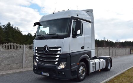
Actros is a family of large trucks and tractors with GVW from 18 to 25 tons. They are produced since 1996. In this article, we will take a detailed look at the fuse box diagrams for the Mercedes Actros (4th Gen; MP4) 2013, 2014, 2015, 2016 , 2017, 2018 years of manufacture.
Here you will find the locations and photos of distribution boxes. The fuses responsible for the “Cigarette lighter” and “Fuel Pump” are highlighted in bold.
In the cabin
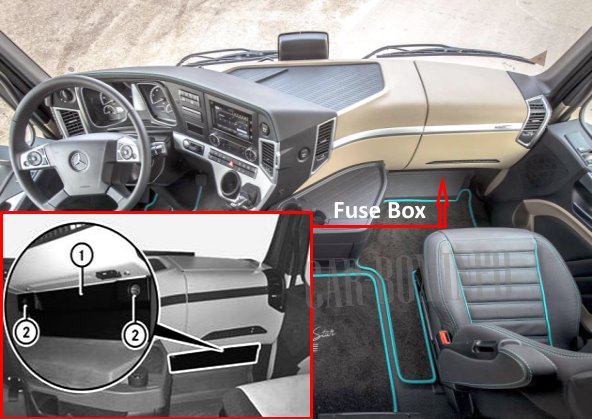
It is located on the passenger side in the lower part of the dashboard. To access the distribution box, unscrew the clips (2) and remove the protective cover (1).
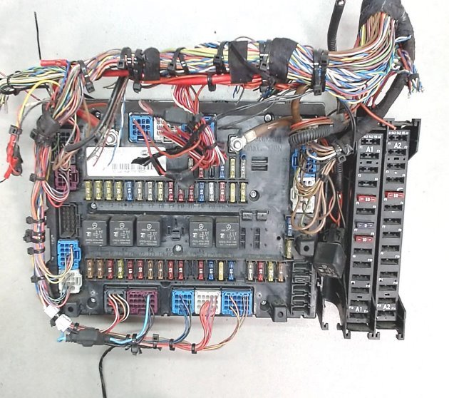
Photo - example of block execution.
Type 1
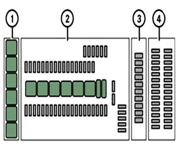
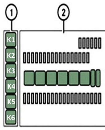
| General arrangement of components on the unit | |
|
|
| 1 | Relay board A32 |
| 2 | Main board (GM) |
| 3 | Relay board A31. |
| 4 | Additional fuse sections A1 and A2. |
| GM main fuse board diagram (SSAM version) | ||
|---|---|---|

|
||
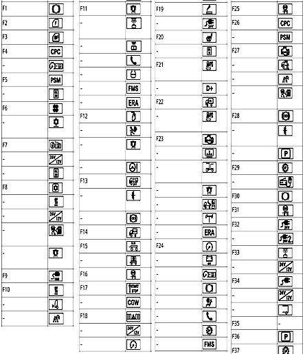
| No. | Description | Amps |
| F1 | Brake system - terminal 30.1 | 20 |
| F2 | Diagnostic connector | 10 |
| F3 | Additional heating system | 15 |
| - | Control unit of the system of adaptive prediction of driving parameters | 15 |
| - | 12V voltage transformer | 15 |
| F4 | Toll Collect System | 10 |
| - | Steering angle sensor | 10 |
| - | Phone | 10 |
| - | Fleet management system | 10 |
| - | Tire pressure monitoring system | 10 |
| - | Auxiliary compartment lights in the rear of the vehicle - terminal 30 | 10 |
| - | ERA‒GLONASS | 10 |
| F5 | LSVA (heavy duty charges based on vehicle capacity) | 15 |
| - | Sliding sunroof | 15 |
| - | EDW system (anti-theft alarm system) | 15 |
| - | CB service radio | 15 |
| F6 | Heating system | 10 |
| - | Driver assistance system | 10 |
| - | Reading lamp - terminal 30 | 10 |
| - | distance sensor | 10 |
| F7 | Electronic air preparation unit - terminal 30 | 20 |
| F8 | Ground clearance control system | 25 |
| - | retarder | 25 |
| F9 | body electrical equipment - terminal 15 | 10 |
| - | Toll Collect System | 10 |
| - | BlueTec® exhaust gas neutralization system | 10 |
| - | ERA‒GLONASS | 10 |
| F10 | Trailer brake light | 20 |
| - | Bodybuilder installed brake light | 20 |
| F11 | Programmable special module | 20 |
| - | Refrigeration box terminal 30 | 20 |
| F12 | Driving mode control system | 20 |
| - | Tachograph - terminal 30 | 20 |
| F13 | 12V voltage transformer | 25 |
| - | Radio/Navigation - Terminal 30 | 25 |
| - | Hydraulic clutch (retarder turbo clutch) | 25 |
| F14 | body - terminal 30 | 10 |
| F15 | Transmission control - terminal 30.1 | 15 |
| F16 | Trailer ABS | 10 |
| F17 | Spare | |
| F18 | Seat heating system | 15 |
| F19 | Spare | |
| F20 | 24V high power power socket | 25 |
| - | Body electrical equipment of another manufacturer | 15 |
| - | CB service radio | 15 |
| F21 | Fuel pre-filter heating system with water separator | 15 |
| - | Distributor - terminal D+ | 15 |
| F22 | Bodybuilder - Terminal D+ | 10 |
| Fuel pre-filter heating system with water separator | 10 | |
| F23 | Spare | |
| F24 | Spare | |
| F25 | Trailer ABS | 20 |
| F26 | Trailer | 20 |
| Trailer voltage transformer - terminal 30 | 20 | |
| F27 | Driver's door control unit | 20 |
| F28 | Spare | |
| F29 | Front passenger door control unit | 20 |
| F30 | Spare | |
| F31 | Spare | |
| F32 | Ceiling lamps for additional compartment on the roof | 10 |
| - | Voltage transformer with remote output | |
| F33 | 24V power sockets | 25 |
| - | Additional 24V power socket | 25 |
| F34 | Spare | |
| F35 | Fan | 25 |
| F36 | Auxiliary hydraulic drive (HAD) | 5 |
| - | MEILLER retrofit mounting socket | 5 |
| - | Tachograph | 5 |
| - | instrument cluster | 5 |
| - | Brake system | 5 |
| - | Additional headlight | 5 |
| - | Safety airbag | 5 |
| - | LSVA (heavy duty charges based on vehicle capacity) | 5 |
| - | Control unit of the system of adaptive prediction of driving parameters | 5 |
| - | Phone | 5 |
| - | Fleet management system | 5 |
| - | Gearbox control system | 5 |
| - | Battery disconnector - terminal 15 | 5 |
| F37 | Brake system - terminal 30.2 | 20 |
| F38 | Driver assistance system | 10 |
| - | Reversing camera | 10 |
| - | Motor control - terminal 15 | 10 |
| - | Swap body - terminal 15 | 10 |
| F39 | Transmission control system - terminal 30.2 | 15 |
| F40 | Driving mode control system | 10 |
| - | Parameterizable special module - terminal 15 | 10 |
| F41 | retarder | 10 |
| - | Electronic air preparation unit - terminal 15 | 10 |
| F42 | Cigarette lighter fuse Mercedes Actros MP4 | 5 |
| - | 15A Power outlet | 15 |
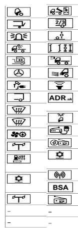
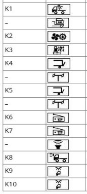
| K1 | Spare | |
| K2 | Amplification - terminal D+ | |
| K3 | Oil cooled gearbox | |
| K4 | Gain - terminal 15 | |
| K5 | ||
| K6 | Trailer brake light | |
| K7 | Amplification - terminal 15 | |
| K8 | bistable relay | |
| K9 | ||
| GM main fuse board diagram (SCA version) | ||
|---|---|---|
|
||
| No. | Description | Amps |
| F2 | Driver's door control unit | 20 |
| F3 | Front passenger door control unit | 20 |
| F4 | Driving mode control system | 20 |
| - | Tachograph - terminal 30 | 20 |
| F5 | Programmable special module | 15 |
| - | Distributor - terminal 30 | 15 |
| F6 | Fan | 25 |
| - | Independent operation electric air conditioning system | 25 |
| F7 | Radio/navigation system | 25 |
| - | 12V voltage transformer | 25 |
| - | Distributor - terminal 30 | 25 |
| F8 | Refrigeration box | 20 |
| - | Additional heating system | 20 |
| - | 12V voltage transformer | 20 |
| - | Adaptive driving prediction system control unit - terminal 30 | 20 |
| - | LSVA (heavy duty charges based on vehicle capacity) | 20 |
| F9 | Diagnostic connector | 10 |
| F10 | Heating system | 10 |
| - | distance sensor | 10 |
| - | Driver assistance system - terminal 30 | 10 |
| F11 | Toll Collect System | 10 |
| - | Auxiliary compartment lights in the rear wall | 10 |
| - | Reading lamp | 10 |
| - | Phone | 10 |
| - | Tire pressure monitoring system | 10 |
| - | Fleet management system - terminal 30 | 10 |
| - | ERA‒GLONASS | 10 |
| F12 | Sliding sunroof | 15 |
| - | EDW system (anti-theft alarm system) | 15 |
| - | LSVA (heavy duty charges based on vehicle capacity) | 15 |
| - | Steering angle sensor | 15 |
| F13 | Ground clearance control system | 25 |
| - | Hydraulic Clutch (Retarder Turbo Clutch) | 25 |
| - | retarder | 25 |
| F14 | Bodybuilder - terminal 30 | 10 |
| F15 | Trailer | 20 |
| - | Trailer voltage transformer - terminal 30 | 20 |
| F16 | Trailer ABS - terminal 30 | 20 |
| F17 | Ignition lock | 5 |
| - | Central Gateway | 5 |
| F18 | Modular Switch Panel | 5 |
| - | Voltage transformer with remote output | 5 |
| - | Instrument cluster - terminal 30 | 5 |
| F19 | cigarette lighter fuse | 6 |
| - | Power socket - terminal 15 | 15 |
| F20 | Seat heating system | 20 |
| - | Distributor - terminal 15 | 20 |
| F21 | Fuel pre-filter heating system with water separator | 15 |
| - | Distributor - terminal D+ | 15 |
| F22 | Bodybuilder - Terminal D+ | 10 |
| - | Fuel pre-filter heating system with water separator | 10 |
| F23 | BlueTec® exhaust aftertreatment system | 5 |
| - | sunblind | 5 |
| - | Traction coupling (low-mounted coupling system) | 5 |
| - | Toll Collect System | 5 |
| - | MEILLER retrofit mounting socket | 5 |
| - | Additional hydraulic drive (HAD) - terminal 15 | 5 |
| - | ERA‒GLONASS | 5 |
| F24 | instrument cluster | 5 |
| - | Battery disconnector | 5 |
| - | Tachograph | 5 |
| - | Brake system | 5 |
| - | Safety airbag | 5 |
| - | Phone | 5 |
| - | Gearbox control system | 5 |
| - | Fleet management system | 5 |
| - | Additional headlight | 5 |
| F25 | Trailer ABS | 10 |
| F26 | Driving mode control system | 10 |
| - | Parameterizable special module - terminal 15 | 10 |
| F27 | Motor control - terminal 15 | 10 |
| - | Reversing camera | 10 |
| - | Driver assistance system | 10 |
| - | Adaptive driving parameter prediction control unit - terminal 15 | 10 |
| F28 | retarder | 10 |
| - | Hydraulic Clutch (Retarder Turbo Clutch) | 10 |
| - | Electronic air preparation unit - terminal 15 | 10 |
| F29 | Transmission control - terminal 30.1 | 15 |
| - | CB service radio | 15 |
| F30 | Brake system - terminal 30.2 | 20 |
| F31 | Trailer brake light | 15 |
| F32 | 24V power sockets | 25 |
| - | Additional 24V power socket | 25 |
| F33 | Roof compartment auxiliary compartment illumination lamps | 10 |
| - | Voltage transformer with remote output | 10 |
| F34 | 24V high power power socket | 25 |
| - | 12V voltage transformer | 25 |
| - | Body electrical equipment of another manufacturer | 15 |
| F35 | Spare | |
| F36 | Electronic air preparation unit - terminal 30 | 20 |
| F37 | Transmission control - terminal 30.2 | 15 |
| K1 | Amplification - terminal 15 | |
| K2 | Amplification - terminal D+ | |
| K3 | Amplification - terminal 15 | |
| K4 | Oil cooled gearbox | |
| K5 | Amplification - terminal 15 | |
| K6 | Trailer brake light | |
| K7 | bistable relay | |
| K8 | ||
| K9 | Spare | |
| Additional fuse sections A1 and A2. | ||
|---|---|---|
|
||
| No. | Description | Amps |
| A1 board | ||
| F1 | Cab Tipper Pump | 5 |
| F2 | tail lift | 10 |
| F3 | Flashing light | 10 |
| F4 | Working headlight | 10 |
| - | swap body | 10 |
| F5 | Illuminated three-pointed star "Mercedes-Benz" | 10 |
| - | Hand lamp socket | 10 |
| F6 | Body electrical equipment of another manufacturer | 15 |
| F7 | Windshield heating system | 25 |
| F8 | 25 | |
| F9 | Oil cooled transfer case | 10 |
| - | Auxiliary hydraulic drive (HAD) | 10 |
| F10 | Fuel pre-filter heating system with water separator | 15 |
| F11 | Independent electric air conditioning system | 20 |
| F12 | Auxiliary hydraulic drive (HAD) | 15 |
| F13 | Spare | |
| F14 | Spare | |
| A2 board | ||
| F1 | Mounting socket for MEILLER retrofits | 10 |
| F2 | Body electrical equipment of another manufacturer 2 and 3 | 20 |
| - | Body auxiliary axle switch | 20 |
| F3 | Managed auxiliary axle | 10 |
| F4 | Additional headlight | 15 |
| F5 | Air control system | 10 |
| F6 | Subwoofer | 10 |
| F7 | Equipment in accordance with the rules for the carriage of dangerous goods by road, for England | 5 |
| F8 | Low roof interior lighting | 5 |
| F9 | CB service radio | 5 |
| F10 | Radio/navigation system | 15 |
| F11 | Independent electric air conditioning system | 5 |
| - | Antenna amplifier | 5 |
| - | cornering assistant | 5 |
| F12 | 12V radio receiver | 10 |
| F13 | Spare | |
| F14 | Spare | |
| Relay board A31 | |
|---|---|
|
|
| No. | Description |
| K1 | Working headlight |
| - | swap body |
| K2 | Oil cooled transfer case |
| K3 | Fuel pre-filter heating system with water separator |
| K4 | Lift board |
| - | Disable Auxiliary Hydraulic Drive (HAD) |
| K5 | Lift board |
| - | Disable Auxiliary Hydraulic Drive (HAD) |
| K6 | 12V radio - terminal 58 |
| K7 | 12V radio - terminal 15R |
| - | Subwoofer |
| K8 | Additional headlight - terminal 58 |
| K9 | Interior lighting with low roof |
| K10 | |
| Relay board A32 | |
|---|---|
|
|
| No. | Purpose |
| K1 | Windshield heating system |
| K2 | |
| K3 | Additional headlight - terminal 56a |
| K4 | Spare |
| K5 | |
| K6 | |
Type 2

Description of elements.
