Opel Insignia is a mid-size car by Opel, replacing the Vectra model. It is produced since November 2008. In the UK it is known under the brand name Vauxhall, in North America and China - as Buick Regal. In this article, we will take a detailed look at the fuse box diagrams for the Opel / Vauxhall Insignia A (first generation) 2008, 2009, 2010, 2011, 2012, 2013, 2014, 2015, 2016 years of manufacture.
Here you will find the locations and photos of distribution boxes. The fuses responsible for the “Cigarette lighter” and “Fuel Pump” are highlighted in bold.
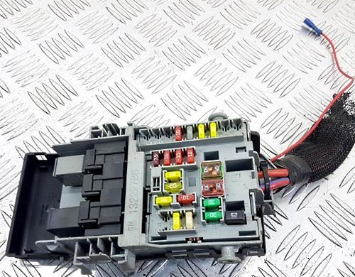
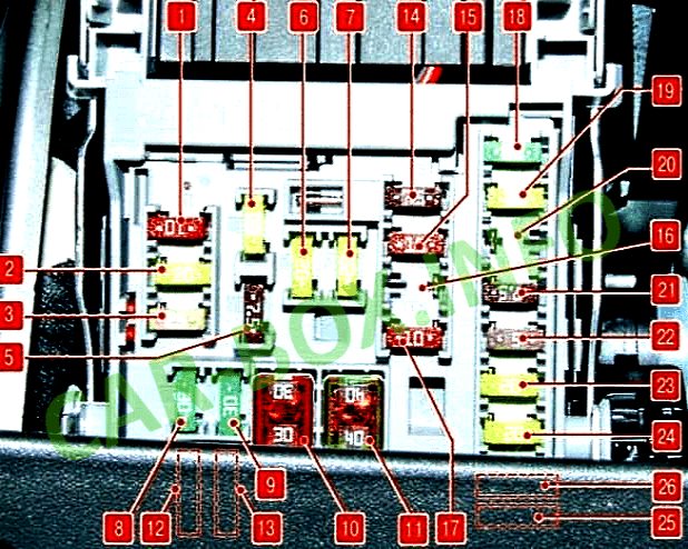
In the trunk
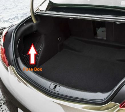
The distribution box is located on the left side behind the trim.
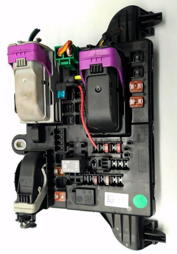
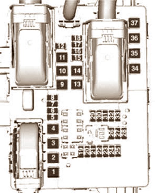
General view.
| Diagram | ||
|---|---|---|
|
||
| No. | Description | Amps |
| 1 | Central locking, electric tailgate | 30 |
| 2 | Air conditioner/heater | 40 |
| 3 | Trailer electrical control unit | 40 |
| 4 | Not used | - |
| 5 | Trailer electrical connector | 30 |
| 6 | Reserve | - |
| 7 | - | |
| 8 | Trailer electrical connector | 30 |
| 9 | Not used | - |
| 10 | Coolant heater | 30 |
| 11 | Power front seats | 30 |
| 12 | Power seat memory | 10 |
| 13 | Headlight range adjustment, level control system | - |
| 14 | Not used | - |
| 15 | - | |
| 16 | - | |
| 17 | Seat heater | - |
| 18 | Rear door electrical control unit (trunk) | 20 |
| 19 | Rear window blind | - |
| 20 | Driver's seat fan | - |
| 21 | Trailer electrical control unit | 7.5 |
| 22 | Rear window blind | 15 |
| 23 | Anti-theft system | 5 |
| 24 | Left parking light | - |
| 25 | Right parking light | - |
| 26 | Lighting, direction indicators | - |
| 27 | ||
| 28 | Not used | - |
| 29 | Transport fuse | 30 |
| 30 | 30 | |
| 31 | Active damping system, automatic high beam, cruise control, traffic sign detection system, lane departure detection system | 10 |
| 32 | Parking system | - |
| 33 | Differential lock control unit, four-wheel drive | 10 |
| 34 | Sunroof | 30 |
| 35 | central locking | 30 |
| 36 | Power front seats | - |
| 37 | Reserve | - |
In the passenger compartment
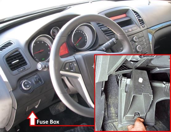
The distribution box is located on the driver's side under the dashboard, behind the glove compartment.
General view of the Insignia A interior fuse box.
| Opel Insignia interior block fuse diagram | ||
|---|---|---|
|
||
| No. | Decoding | Amps |
| 1 | A22 Radio receiver control K33 Driver Information Center (DIC) display |
10 |
| 2 | K9 Body Control Module, Exterior Lighting | 20 |
| 3 | K9 Body Control Module | 25 |
| 4 | A11 Radio receiver, P5 Buzzer control unit |
20 |
| 5 | A12 Digital radio control unit, K82 Cell phone control unit, T11 Multimedia player interface module |
7.5 |
| 6 | Front power socket (Opel / Vauxhall Insignia A cigarette lighter fuse) | 20 |
| 7 | Power outlet for optional equipment | 20 |
| 8 | Left headlight (dipped beam, halogen) | 30 |
| 9 | Right headlight (dipped beam, halogen) | 30 |
| 10 | Door locks | 30 |
| 11 | K8 Fan motor control module. Heating (ventilation) and air conditioning system | 40 |
| 12 | S64D Seat position adjuster switch - driver, S65D Seat lumbar support switch - driver | 25 |
| 13 | Power front seats | 25 |
| 14 | X84 Diagnostic connector | 7.5 |
| 15 | Airbag Diagnostic and Monitoring Module K36 | 7.5 |
| 16 | central locking | 10 |
| 17 | HVAC system control panel and control unit | 10 |
| 18 | KR104A Logistic mode relay 1 | 30 |
| 19 | Stop lights, light bulbs | 20 |
| 20 | K85 Passenger presence detection module | 5 |
| 21 | P16 dashboard | 10 |
| 22 | S39 Ignition switch | 5 |
| 23 | K9 Body Control Module | 20 |
| 24 | 20 | |
| 25 | Steering column lock | 20 |
| 26 | Power connector for optional equipment | 20 |
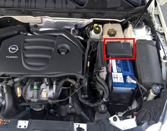
In the underhood
Here there are two blocks responsible for the protection of the car's electrical circuits.
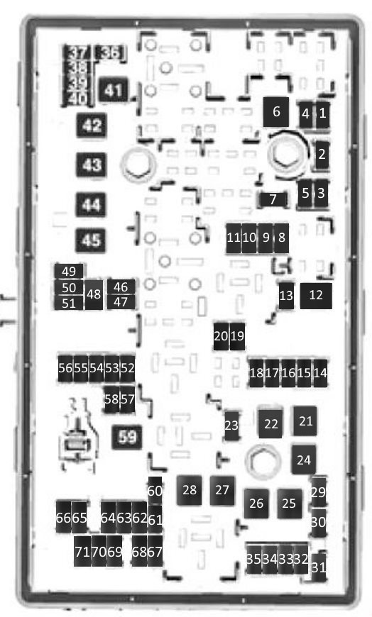
Fuse box
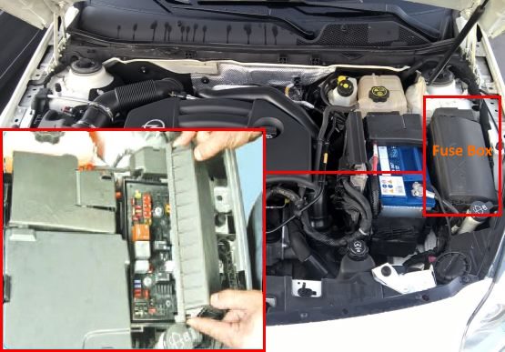
It is located near the battery, on the left. It is covered with a plastic cover.
| Diagram | ||
|---|---|---|
|
||
| No. | Description | Amps |
| 1 | Transmission control unit | 5 |
| 2 | Electronic engine control unit | 15 |
| 3 | Reserve | - |
| 4 | - | |
| 5 | Ignition, transmission control unit, engine control unit | 15 |
| 6 | Windshield cleaner | 30 |
| 7 | — | - |
| 8 | Engine management, Fuel injection, ignition system | 15 |
| 9 | 15 | |
| 10 | Electronic engine control unit | 15 / 20 |
| 11 | Engine control | 10 |
| 12 | Starter | 30 |
| 13 | Throttle sensor heating | 7.5 |
| 14 | Lighting | 15 |
| 15 | Rear window wiper | 20 |
| 16 | Engine control | 7.5 |
| 17 | Ignition, airbag | 5 |
| 18 | Adaptive headlights | 15 |
| 19 | 15 | |
| 20 | Fuel module (gasoline pump) | 20 |
| 21 | Power windows | 30 |
| 22 | ABS,ESP | 30 |
| 23 | Power steering | 10 |
| 24 | Electric windows | 30 |
| 25 | Plug sockets | 30 |
| 26 | ABS, ESP system | 60 |
| 27 | Parking brake (handbrake) | 30 |
| 28 | Rear window defroster | 40 |
| 29 | Left seat with electric adjustment system | 15 |
| 30 | Right seat with electric adjustment system | 15 |
| 31 | Air conditioner compressor solenoid clutch | 10 |
| 32 | Multifunction control unit | 20 |
| 33 | Front seat heater | 25 |
| 34 | Roof ventilation hatch | 25 |
| 35 | Audio amplifier | 30 |
| 36 | Reserve | - |
| 37 | High beam right headlight | 10 |
| 38 | Left high beam | 10 |
| 39 | Reserve | - |
| 40 | Liquid pump | - |
| 41 | Vacuum pump | 30 |
| 42 | Cooling fan motor | 60 |
| 43 | Reserve | - |
| 44 | Headlight washers | 25 |
| 45 | Cooling fan motor | 60 |
| 46 | 10 | |
| 47 | Engine control | 10 |
| 48 | Fog lights | 15 |
| 49 | Dipped beam lamp, right headlight | 15 |
| 50 | Left dipped beam lamp | 15 |
| 51 | Horn | 15 |
| 52 | Instrument cluster, signal | 5 |
| 53 | Ignition | 10 |
| 54 | Headlight switch | 5 |
| 55 | Power windows and folding mirrors | 7.5 |
| 56 | Windshield washer pump motor | 15 |
| 57 | Steering column lock | 15 |
| 58 | Spare | - |
| 59 | Diesel fuel heating | - |
| 60 | Power mirrors | 7.5 |
| 61 | 7.5 | |
| 62 | Evaporative emission system | 10 |
| 63 | Rear window heating sensor | 7.5 |
| 64 | Adaptive headlights | 5 |
| 65 | Anti-theft siren | 7.5 |
| 66 | Rear window washer pump motor | 15 |
| 67 | Fuel pump fuse | 20 |
| 68 | Reserve | - |
| 69 | Multifunction control unit | 5 |
| 70 | Rain sensor | 5 |
| 71 | Power supply for electronic bodywork equipment | - |
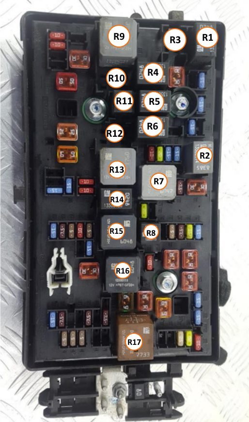
| Assignment of relay modules in the unit | |
|
|
| No. | Description |
| R1 | A/C compressor magnetic clutch relay |
| R2 | Starter relay |
| R3 | - |
| R4 | - |
| R5 | - |
| R6 | - |
| R7 | Engine control relay |
| R8 | Fuel pump relay |
| R9 | - |
| R10 | - |
| R11 | Headlight washer pump relay |
| R12 | - |
| R13 | - |
| R14 | - |
| R15 | Relay for main ignition circuits |
| R16 | Exhaust air pump relay |
| R17 | Rear window heater relay |
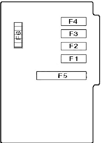
Power fuse block
Located on the battery cover.
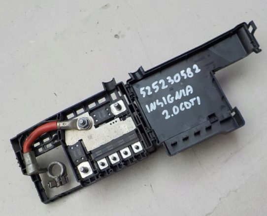
General view.
| Diagram | ||
|---|---|---|
|
||
| No. | Purpose | Amps |
| F1 | Cabin fuse box | 100 |
| F2 | 100 | |
| F3 | Fuse box in trunk | 100 |
| F4 | 100 | |
| F5 | Alternator / Starter | 250 |
| F6 | 250 / 300 500 |
|
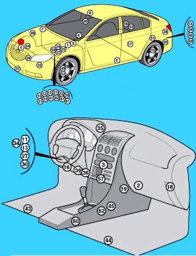
All electronic modules
General layout of the electrical equipment.
|
|
| No. | Component |
| 1 | ABS unit |
| 2 | Air conditioner/heater fan motor control unit - near heater fan motor |
| 3 | Air conditioner/heater control unit - behind the heater control panel |
| 4 | Shock sensor (SRS) |
| 5 | Side impact sensor, left |
| 6 | Side impact sensor, right |
| 7 | Anti-theft alarm sound |
| 8 | Anti-theft system control unit (with volume change control) - on the roof panel |
| 9 | Anti-theft siren |
| 10 | Anti-theft relay - built into the engine compartment fuse/relay box |
| 11 | Accessory power connector relay - in fuse/interior relay box |
| 12 | battery |
| 13 | Trunk lid opener relay - in fuse box / relay under dashboard |
| 14 | Fuel filler flap lock actuator relay - in fuse box/relay in luggage compartment |
| 15 | Central locking relay (driver's door) - built into the fuse/relay box in the engine compartment 1 |
| 16 | Diagnostic connector (DLC) |
| 17 | Differential lock control unit - on the rear gearbox |
| 18 | Audio system (DAB) receiver - behind the glove compartment |
| 19 | Additional electric heater - on the heater fan housing |
| 20 | Electric parking brake control unit - behind the wheel arch |
| 21 | Electronic engine control unit - near the battery |
| 22 | Fog light relay - built into fuse/relay box in engine compartment 1 |
| 23 | Fuse box, engine compartment 1 |
| 24 | Power distribution box for battery |
| 25 | Fuse box 3 - near the battery |
| 26 | Fuse Box 4 - Near Cooling Fan Motor |
| 27 | Fuse/Relay Box, Interior - Behind Dashboard, Left |
| 28 | Fuse/relay box, trunk - behind trim |
| 29 | Glow plug control unit - next to the battery |
| 30 | Headlight control unit - behind the dashboard |
| 31 | High beam relay - built into the fuse/relay box in the engine compartment 1 |
| 32 | Horn - behind the front bumper |
| 33 | Horn relay - built into the fuse/relay box in the engine compartment 1 |
| 34 | Auxiliary Ignition Relay 1 - In the under-dash fuse/relay box |
| 35 | Keyless entry signal receiver - behind the instrument cluster |
| 36 | Multifunction control unit - functions:
|
| 37 | Ambient air temperature sensor |
| 38 | Parking Control Module - Behind Luggage Compartment Trim Panel |
| 39 | Power Steering Control Module - Behind Dashboard |
| 40 | Rain sensor - upper center of windshield |
| 41 | Rear window washer pump motor relay - built into fuse/relay box in engine compartment 1 |
| 42 | Rear window wiper motor relay - built into engine compartment fuse/relay box 1 |
| 43 | Seat heating control unit .Left. front - under the seat |
| 44 | Seat heating control unit, right, front. - under the seat |
| 45 | SRS electronic control unit - under the center console |
| 46 | Suspension control unit - behind trim panel |
| 47 | Acceleration sensor 1 - on the suspension cup |
| 48 | Acceleration sensor 2 - on the suspension cup |
| 49 | Acceleration sensor 3 - on suspension |
| 50 | Acceleration sensor 4 - on suspension |
| 51 | Acceleration sensor 5 - under the luggage compartment floor |
| 52 | Body Height Sensor (Left) - Suspension Mounted |
| 53 | Body Height Sensor (Left) - Suspension Mounted |
| 54 | Body Height Sensor (Right) - Suspension Mounted |
| 55 | Rear door electrical control unit (station wagon) - behind the rear door trim panel |
| 56 | Rear door electrical control unit (hatchback) - behind the tailgate trim |
| 57 | Telephone control unit |
| 58 | Trailer electrical control unit - behind the trim panel |
| 59 | Electronic gearbox control unit - on the gearbox |
| 60 | Inverter - under the center console |
| 61 | Windshield washer pump relay - built into the unit in the engine compartment 1 |
| 62 | Lateral movement sensor - under the center console |
